Tubing cutter

a cutter and tube technology, applied in the field of tube cutters, can solve the problems of small hand span, difficult to apply the necessary closing force on the handle, and excessive effort on the part of the user, and achieve the effect of less force and longer cutting strokes

Active Publication Date: 2008-06-19
EMERSON ELECTRIC CO
View PDF19 Cites 17 Cited by
  • Summary
  • Abstract
  • Description
  • Claims
  • Application Information

AI Technical Summary

Benefits of technology

[0006]In accordance with the present application, an improved tubing cutter is provided, especially for plastic tubing of the type mentioned above, which advantageously enables the single stroke of large diameter tubing, such as 1-⅜ inch tubing for example, with less force than heretofore required with regard to closing the handles of the cutter to achieve the cutting operation. More particularly in this respect, the cutter is characterized by a first handle having a cradle for supporting a tube to be cut, a second handle pivotally attached to the first handle, a cutter blade attached to the second handle for displacement therewith and relative thereto, and a pin and slot interengagement between the cutter blade and the first handle by which the angular displacement of the cutter blade from an open to a closed position relative to the cradle is greater than the angular displacement of the handles to achieve such blade displacement. Accordingly, a longer cutting stroke is achieved with a given handle displacement than heretofore possible, thus enabling the cutting of large diameter tubing with a single stroke, one hand manipulation of the cutters by a user.
[0007]In accordance with another aspect of the application, an improved tubing cutter is provided, especially for plastic tubing of the type mentioned above, which advantageously provides a mechanical advantage to users of the tubing cutter. In this aspect of the application, the slot configuration provides for displacement of the blade relative to the cradle to initially apply a higher cutting force which is followed by a transition to a lower cutting force and a higher rate of blade displacement. Accordingly, a user can grasp the open handles of the cutters closer to the pivot axis between the handles to promote a better gripping of the handles and then, when the cutting stroke is in progress, the user can grasp the handles closer to the outer ends thereof and apply the same cutting force as was initially applied with the hands close to the pivot axis. In this respect, as the transition takes place to the lesser cutting force the user's grasping of the handles adjacent the outer ends thereof increases the leverage and thus enables obtaining the initial force in completing the cutting operation.
[0011]A further object is the provision of a tubing cutter of the foregoing character which provides for single stroke cutting of tubing to be achieved with less physical effort than heretofore required on the part of a user.
[0012]Still another object is the provision of a tubing cutter of the foregoing character which provides a high leverage during the initial cutting of a tube followed by lower leverage and a higher cutting rate as the cutting operation is completed.

Problems solved by technology

The scissors-type cutters which require a squeezing action of the handles requires an excessive effort on the part of the user to achieve a cutting operation, especially with larger diameter tubing.
Furthermore, with initially cutting through a larger diameter tube, a user who has a small hand span has difficulty in applying the necessary closing force on the handles to achieve initial cutting of the tube and, often, has to grasp the handles with both hands to initiate cutting.
While the ratchet mechanism allows a smaller stroke of the cutter handles relative to one another for each intermittent cut, whereby a user can operate the cutter without a large hand span, the cutters are structurally complex and a cutting operation requires a number of sequential displacements of the ratchet handle relative to the cutting head to complete a cutting operation, especially with respect to larger diameter tubes.

Method used


Image

  • Tubing cutter
  • Tubing cutter
  • Tubing cutter

Examples


Embodiment Construction

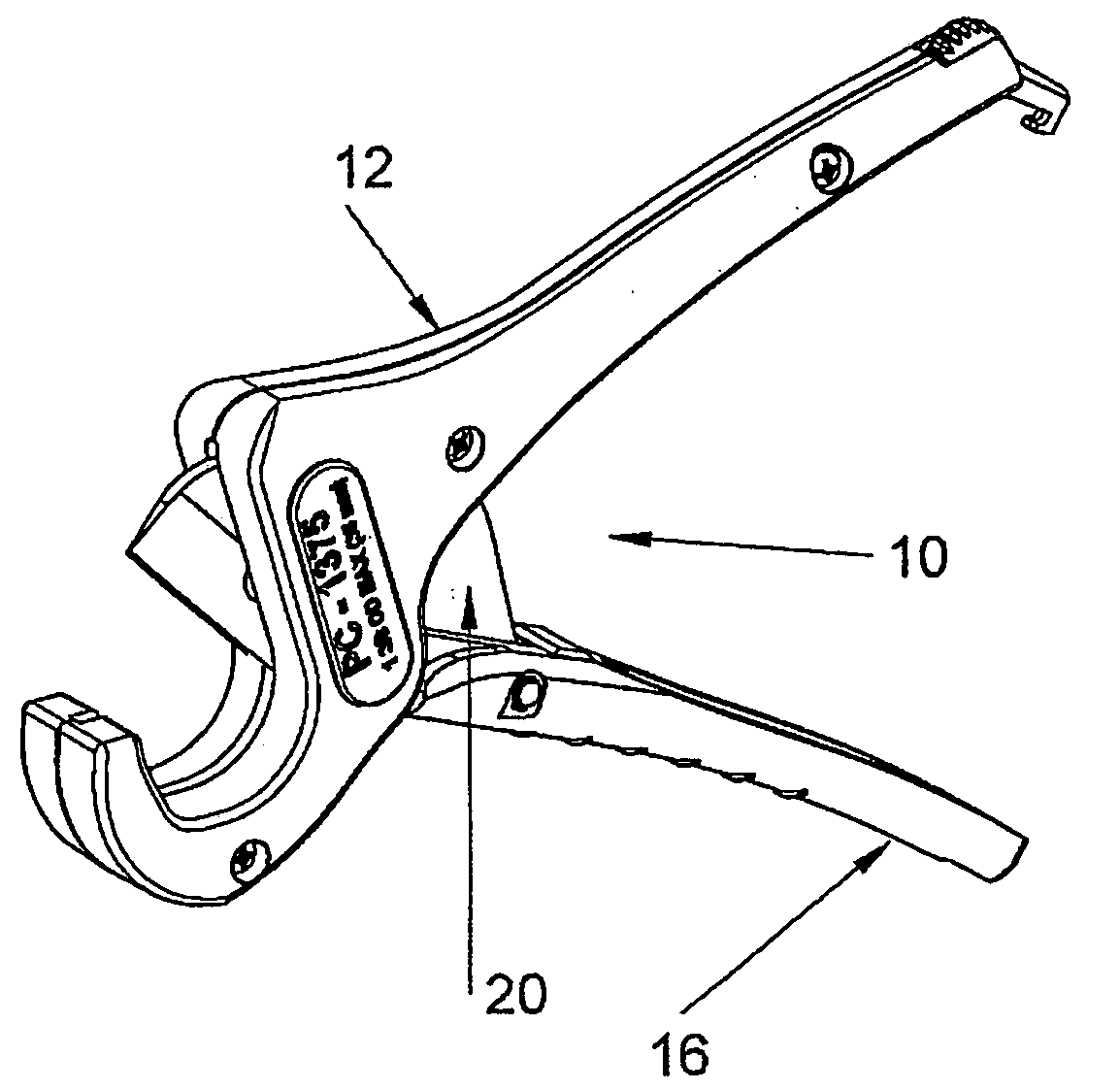
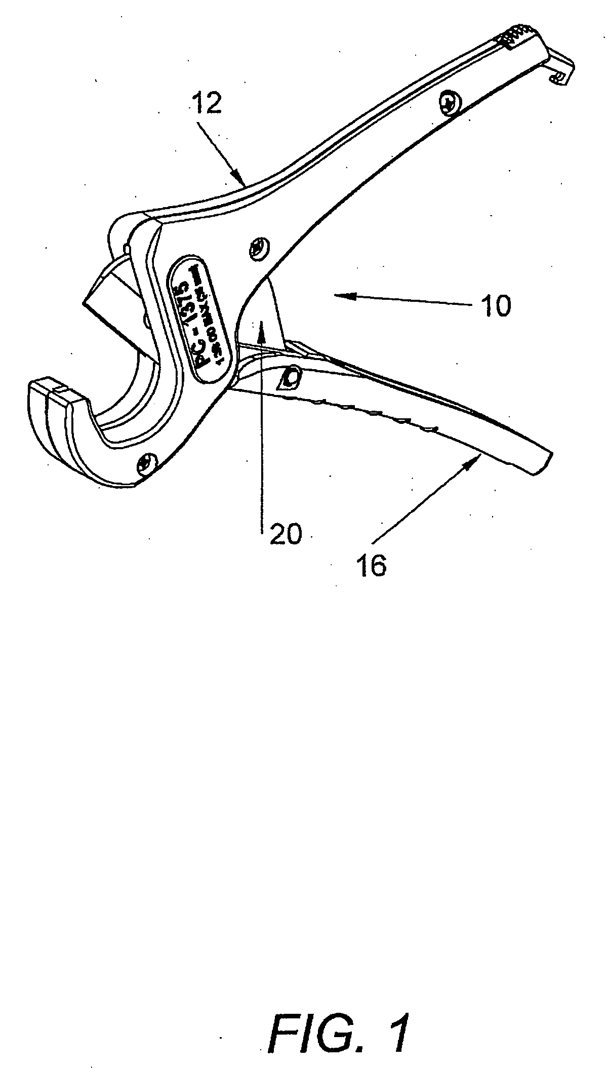
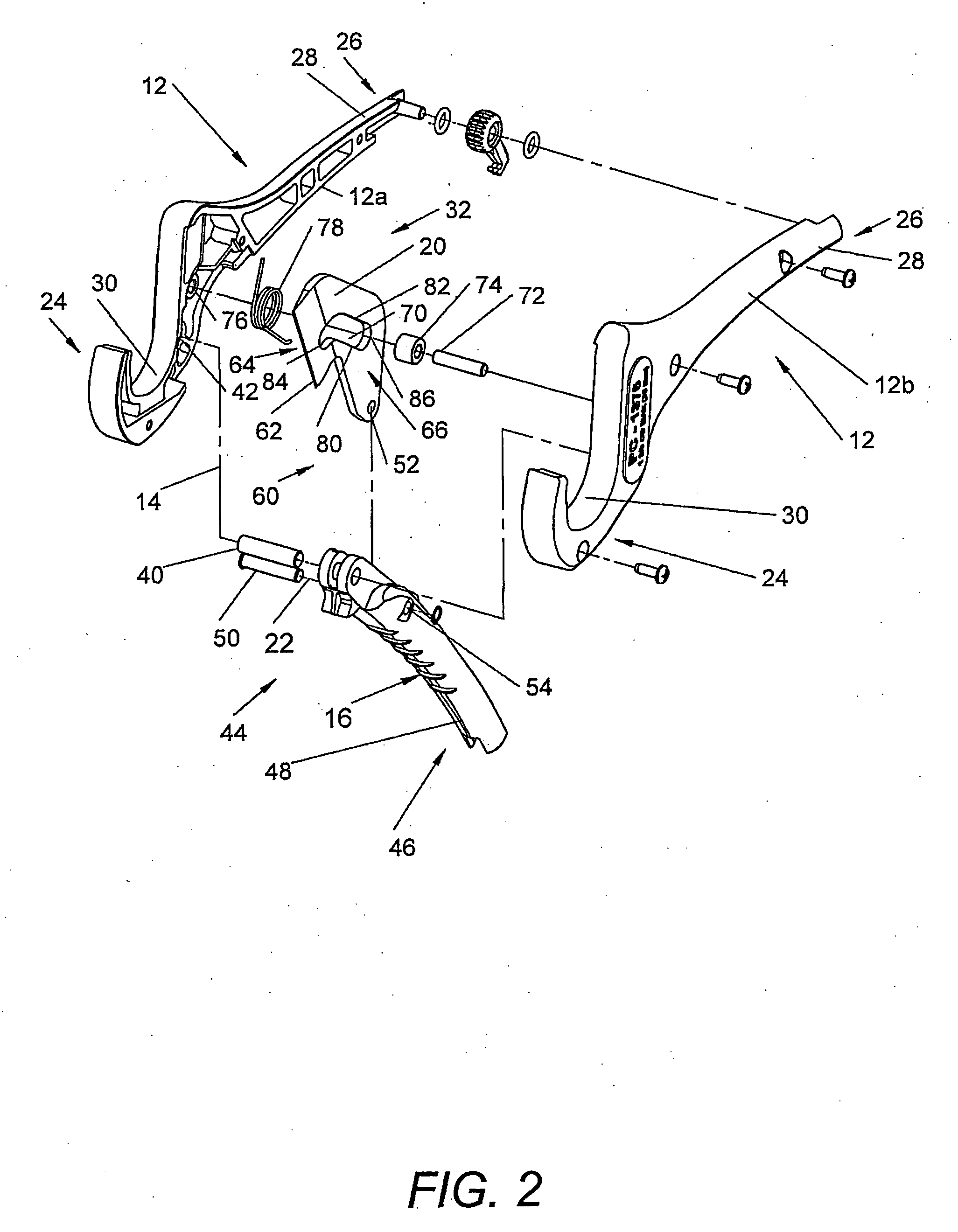
[0020]Referring now in greater detail to the drawings, wherein the showings are for the purpose of illustrating preferred embodiment of the present invention and not for the purpose of limiting the invention, FIG. 1 provides a perspective view of the subject tubing cutter apparatus 10 in a partially opened position and FIG. 2 is an exploded perspective view illustrating the various preferred components thereof and their preferred arrangement in the subject tool.

[0021]As shown in those Figures, the preferred form of the tubing cutter 10 comprises a first elongate member 12 pivotally attached at a handle axis 14 with a second elongate member 16, and a cutter blade 20 pivotally attached at a blade axis 22 with the second elongate member 16 as shown. In the preferred embodiment illustrated, the first elongate member 12 is defined by handle halves 12a and 12b, each of which has a first end 24 and an opposite second end 26. Ends 24 are provided with corresponding arcuate cradle portions 3...


PUM

PropertyMeasurementUnit
angle Φ2aaaaaaaaaa
outer diameteraaaaaaaaaa
angle Φ1aaaaaaaaaa

Abstract

A cutter tool includes first and second elongate members carrying a cutting blade pivotally attached with the second elongate member and slidably attached with the first elongate member to enable cutting an associated tubular workpiece with an increased mechanical advantage with the tool in an opened position. The tool is characterized by a first handle having a cradle for supporting a tube to be cut, a second handle pivotally attached to the first handle, a cutter blade attached to the second handle for displacement therewith and relative thereto, and a pin and slot interengagement between the cutter blade and the first handle by which the angular displacement of the cutter blade from an opened to a closed position relative to the cradle is greater than the angular displacement of the handles to achieve such blade displacement. The slot configuration provides for displacement of the blade relative to the cradle to initially apply a higher cutting force which is followed by a transition to a lower cutting force and a higher rate of blade displacement.

Description

BACKGROUND[0001]This application relates to the art of cutting devices and, more particularly, to improvements in tools for cutting workpieces having a circular cross section such as tubing. Although the preferred embodiment will be described in connection with a manual tubing cutter apparatus for cutting plastic tubes by hand, it is to be appreciated that the invention has application in other areas including devices for cutting, clipping, or otherwise applying a force to associated workpieces.[0002]A wide variety of tubing cutters has been provided heretofore for cutting plastic tubing of the character used in commercial and domestic water systems, such as schedule 40 PVC tubing, for example. Such cutters have included scissors-type cutters such as that shown in U.S. Pat. No. 6,513,245 to Aubriot and U.S. Pat. No. 6,658,738 to King wherein a tube to be cut is supported in a cradle portion of the cutter and a blade is displaceable about a fixed pivot axis to cut a tube interposed b...

Claims


Application Information

Patent Timeline
Patent Type & Authority Applications(United States)
IPC IPC(8): B23D21/06
CPCB26D3/169B26B17/00
Inventor NANDKUMAR, NYAYADHISH SUNILSITACHARAN, PATHAK SANJAYMACHOVINA, DAVID LEEMACSAY, STEVEN MICHAELCHARTIER, GLEN RICHARD
Owner EMERSON ELECTRIC CO
Why Eureka
Try Eureka