Collapsible container

a container and container body technology, applied in the field of plastic containers, can solve the problems of increasing the amount of force required to collapse or expand the container to the point of being less practical to use, and the possibility of substantial leakag

Active Publication Date: 2013-10-24
DART IND INC
View PDF16 Cites 57 Cited by
  • Summary
  • Abstract
  • Description
  • Claims
  • Application Information

AI Technical Summary

Benefits of technology

[0008]A principal object of the present invention is to provide a collapsible container which presents or forms a substantially rigid receptacle in its open or expanded position and which, with an appropriate watertight lid or seal snap-fitted thereto, provides a practical watertight storage container for, as an example, an appropriate beverage, or the like. The container is very convenient and provides a particularly desirable portable solution for drinks “on-the-go”, such as at picnics, lunches for those who take their own lunch to work, and other instances wherein temporary storage of liquids is desired. The collapsible nature of the container, collapsing to a substantially completely compacted configuration of minimal height, particularly with a watertight seal mounted thereon to confine any residue in the now empty container, allows the used container to be conveniently stored or packed away in a “brown bag”, knapsack, picnic hamper, or the like, for subsequent cleaning and reuse.

Problems solved by technology

As the wall elements are not integrally formed and slide freely relative to each other, there is a substantial possibility of leakage, and use, other than as a temporary drinking vessel, is not practical.
One disadvantage of this arrangement, however, is that, as the diameter of the opening in the container decreases, the amount of force required to collapse or expand the container increases to the point of being less practical to use.
With the single molding step described by Owsen, however, there is no possibility to obtain an optimal hardness to softness ratio for the annular sections of a collapsible cup, which can be achieved through the use of two different materials in a multiple injection molding process.

Method used


Image

  • Collapsible container
  • Collapsible container
  • Collapsible container

Examples


first embodiment

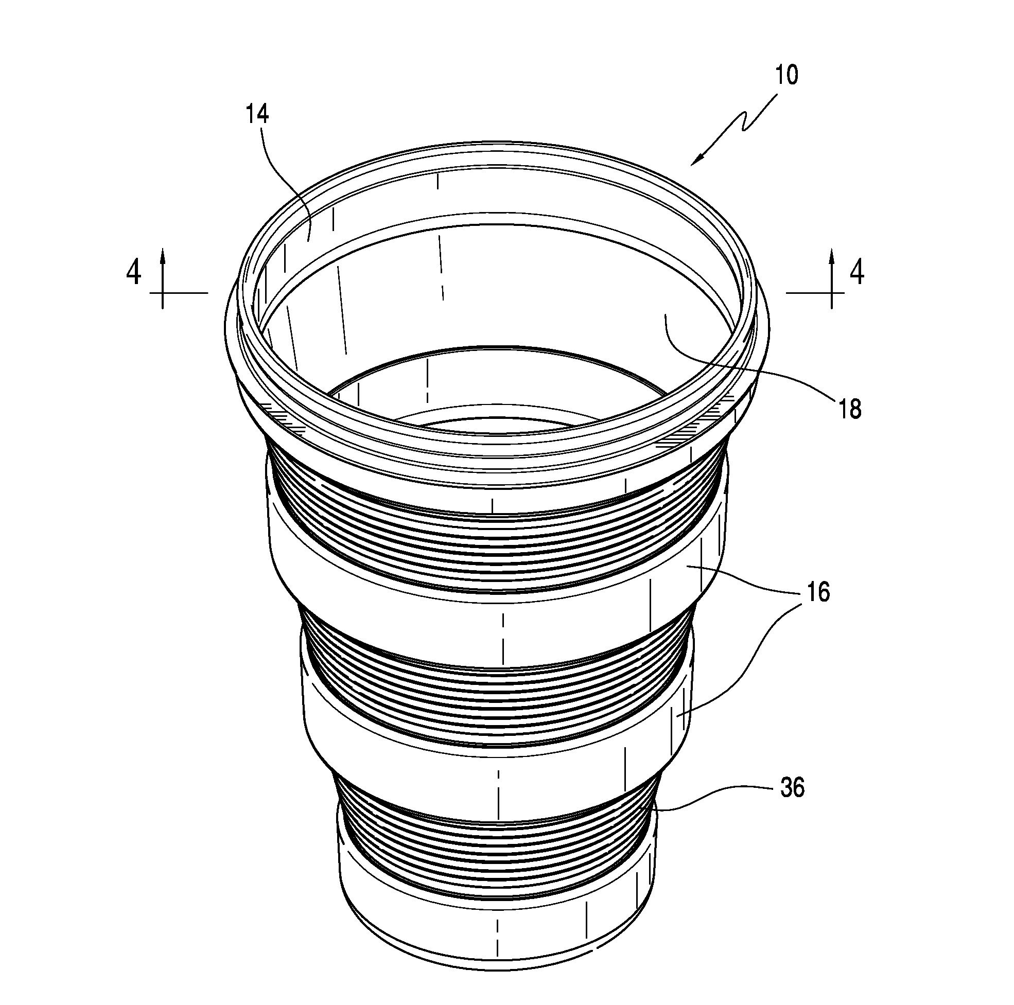
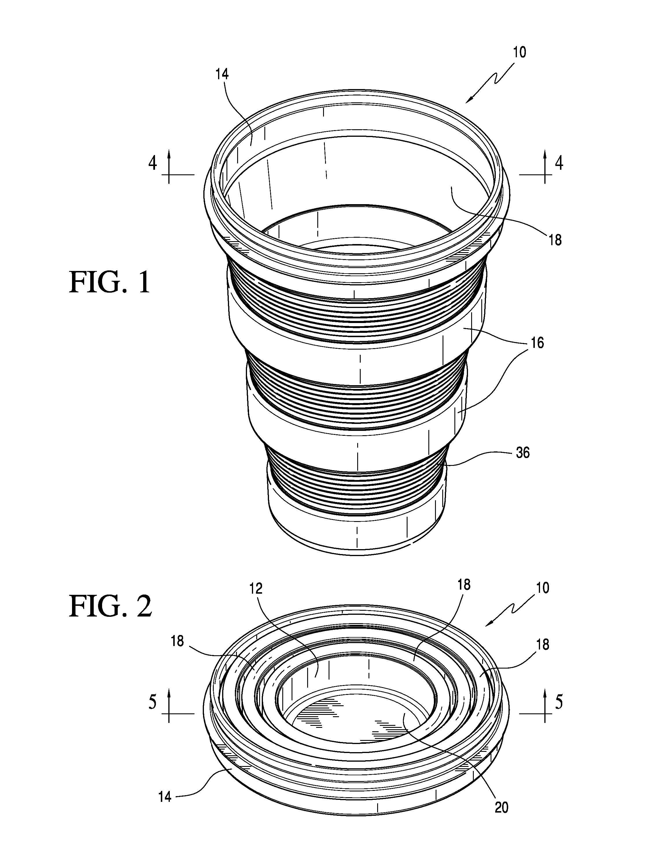
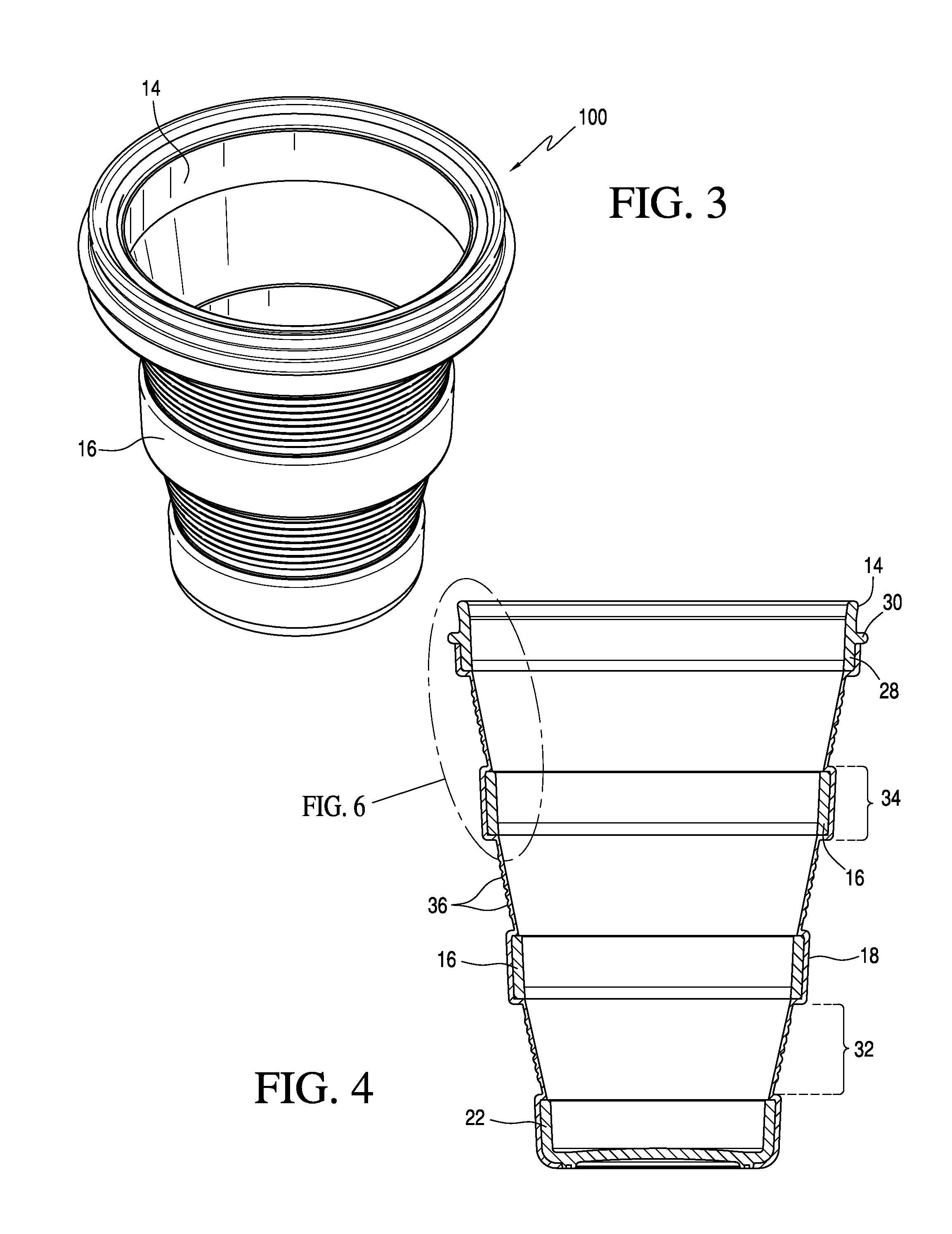
[0047]Referring now more specifically to the drawings, and with particular attention to FIGS. 1, 2 and 4, the collapsible container 10 comprises a base 12, a top ring 14, and a plurality of substantially rigid intermediate rings 16 disposed therebetween. The peripheral wall 18 of the container 10, which extends from the base 12 to the top ring 14, comprises a soft, flexible material that is over-molded to the base 12, top ring 14, and rigid intermediate rings 16, to form the collapsible container 10, as will be described more fully below.

[0048]In an alternative embodiment of the invention, only one intermediate ring 16 is present in the container wall (FIG. 12).

[0049]The flexible material of the peripheral wall 16 may also be defined as being pliable, bendable, and / or foldable.

[0050]The base 12 is a substantially rigid member including a flat bottom 20 and a peripheral upstanding base wall 22.

[0051]Referring now to FIGS. 11A and 11B, the base 20, which preferably may be slightly upw...

second embodiment

[0064]The collapsible container of the invention may also optionally include a foot 24, depending from the base bottom 20, which is preferably molded as a separate component, as shown in FIG. 11B, and then permanently secured to the base 12, for example by bonding or gluing. Optionally, the foot 24 may be integrally molded with the base, as shown in FIG. 11B.

[0065]Referring in particular to FIGS. 17 and 18, it will be noted that each of the flexible wall sections 32 includes corrugations 50A, 50B, 50C, and 50D, in the central area thereof which, in transverse cross section, comprise bands of flexible wall material of different thicknesses, producing a plurality of angled corrugations on the outside surface of the flexible wall sections 32.

[0066]As a result of the angular configuration of the living hinges from one side of the container to the other, the height of the corrugations above and below the upper 58, central 56, and lower 60 living hinges varies from one side of the contain...


PUM

PropertyMeasurementUnit
thicknessaaaaaaaaaa
thicknessaaaaaaaaaa
thicknessaaaaaaaaaa

Abstract

A collapsible container having a rigid base, a rigid top ring, and rigid intermediate rings extending therebetween. A flexible peripheral wall is intimately bonded to the base, top ring, and intermediate rings, to form wall sections having alternating sections of flexible material and flexible material intimately bonded to the intermediate rings, whereby the container is adjustable between an expanded position with the top ring spaced upward from said base and forming a container interior, and a collapsed position with said top ring surrounding said base in outwardly spaced substantially concentric relation thereto.

Description

BACKGROUND OF THE INVENTION[0001]The present invention generally relates to molded plastic containers of the type commonly used for a variety of purposes including storage of both food items and non-food items, such containers preferably being adapted to receive an appropriate seal or lid. More specifically, the invention is concerned with containers of this type which, rather than being of a rigid construction as with a conventional container, are collapsible or foldable to a compact position when empty to facilitate convenient use and storage.[0002]Such containers, in the form of tumblers, cups, bowls, and the like, are generally known in the art and take many forms. These include collapsible cups or glasses wherein the glass is formed of telescopically stacked annular wall elements which slide relative to each other between a fully extended position and a collapsed position. As the wall elements are not integrally formed and slide freely relative to each other, there is a substan...

Claims


Application Information

Patent Timeline
Patent Type & Authority Applications(United States)
IPC IPC(8): B65D8/14B29C45/16
CPCA45F3/20A45F2003/205A47G19/22B29C45/14B65D21/08
Inventor KUSUMA, DAVID D.TRUDEAU, RAYMOND J.BAREA, HECTOR J.
Owner DART IND INC
Why Eureka
Try Eureka