Indicating device

a technology of indicating device and indicating plate, which is applied in the direction of identification means, counting objects on conveyors, instruments, etc., can solve the problems of complex moving parts, high manufacturing cost, and easy assembly of devices, and achieves the effect of less susceptible to damage and easy manufacturing and assembly

Inactive Publication Date: 2005-08-09
TRUDELL MEDICAL INT INC
View PDF311 Cites 60 Cited by
  • Summary
  • Abstract
  • Description
  • Claims
  • Application Information

AI Technical Summary

Benefits of technology

[0016]The present invention provides significant advantages over other aerosol dispensing devices and indicating devices used therewith. In particular, the indicating device can be separately manufactured and installed as needed on any number of conventional types of aerosol containers with little or no required modification to the container or housing. Moreover, the indicating device with its indicator member and drive mechanism is comprised of a relatively few, simple mechanical parts that are relatively easy to manufacture and assemble. In this way, the indicating device is made more robust and is less susceptible to damage when exposed to various adverse user environments. In addition, the drive mechanism and indicator member provide a reliable indicating device for indicating the number of doses dispensed from or remaining in the container, and the indicating device can be made in a relatively compact configuration that does not interfere with the use of the dispensing device.

Problems solved by technology

For example, indicating devices of this nature may include complex moving parts which can be difficult to assemble and expensive to manufacture.
Such devices may also be susceptible to counting inaccuracies due to the configuration of the indexing or mating parts, or require excessive amounts of space within the housing to accommodate the relatively large or numerous moving parts.
Others still may impede or interfere with the airflow and medicament being dispensed from the inhalation device.
Such devices can be relatively expensive to manufacture, however, and typically require a power source which may be susceptible to damage in various environments, such as moist conditions.

Method used


Image

  • Indicating device
  • Indicating device
  • Indicating device

Examples


Embodiment Construction

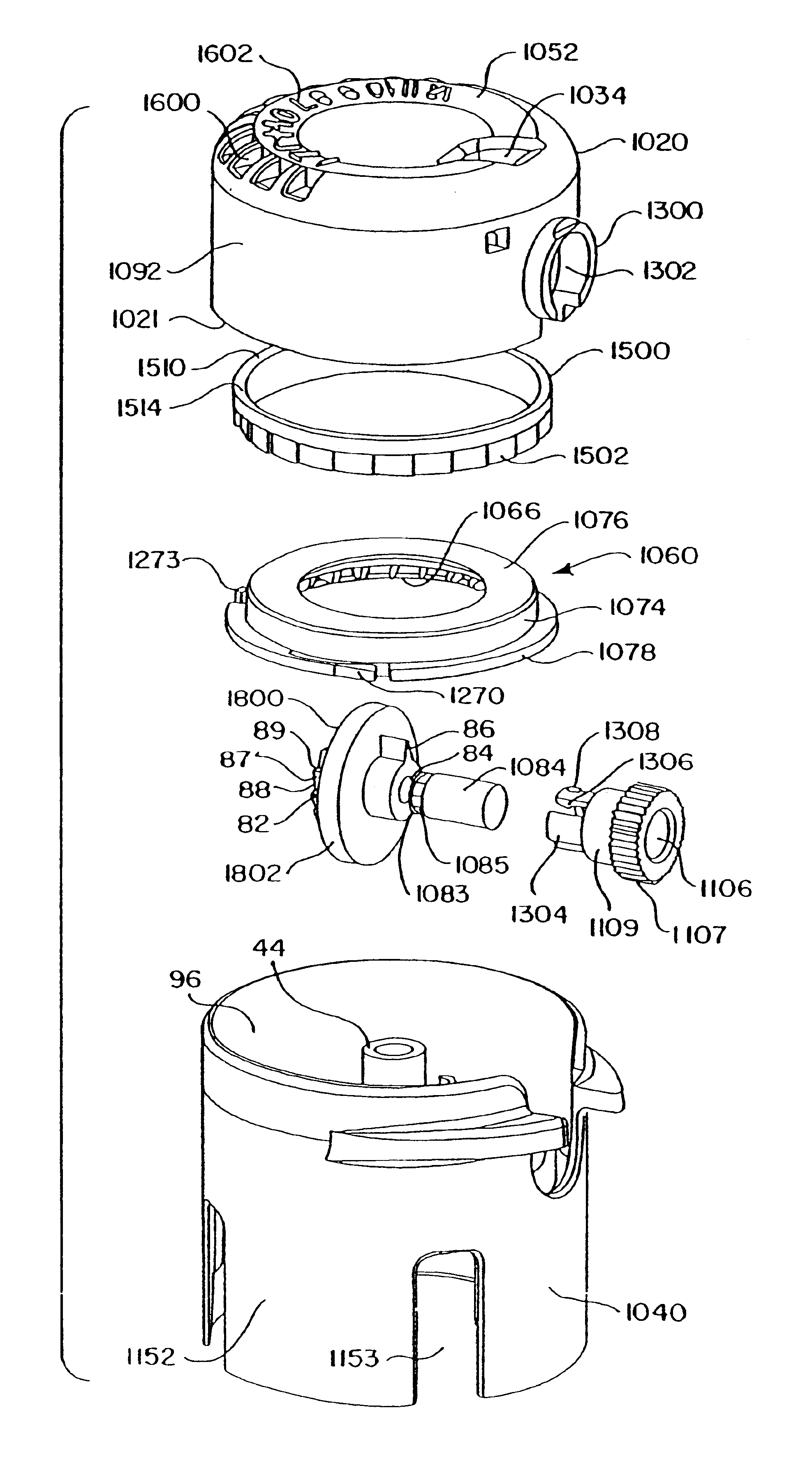
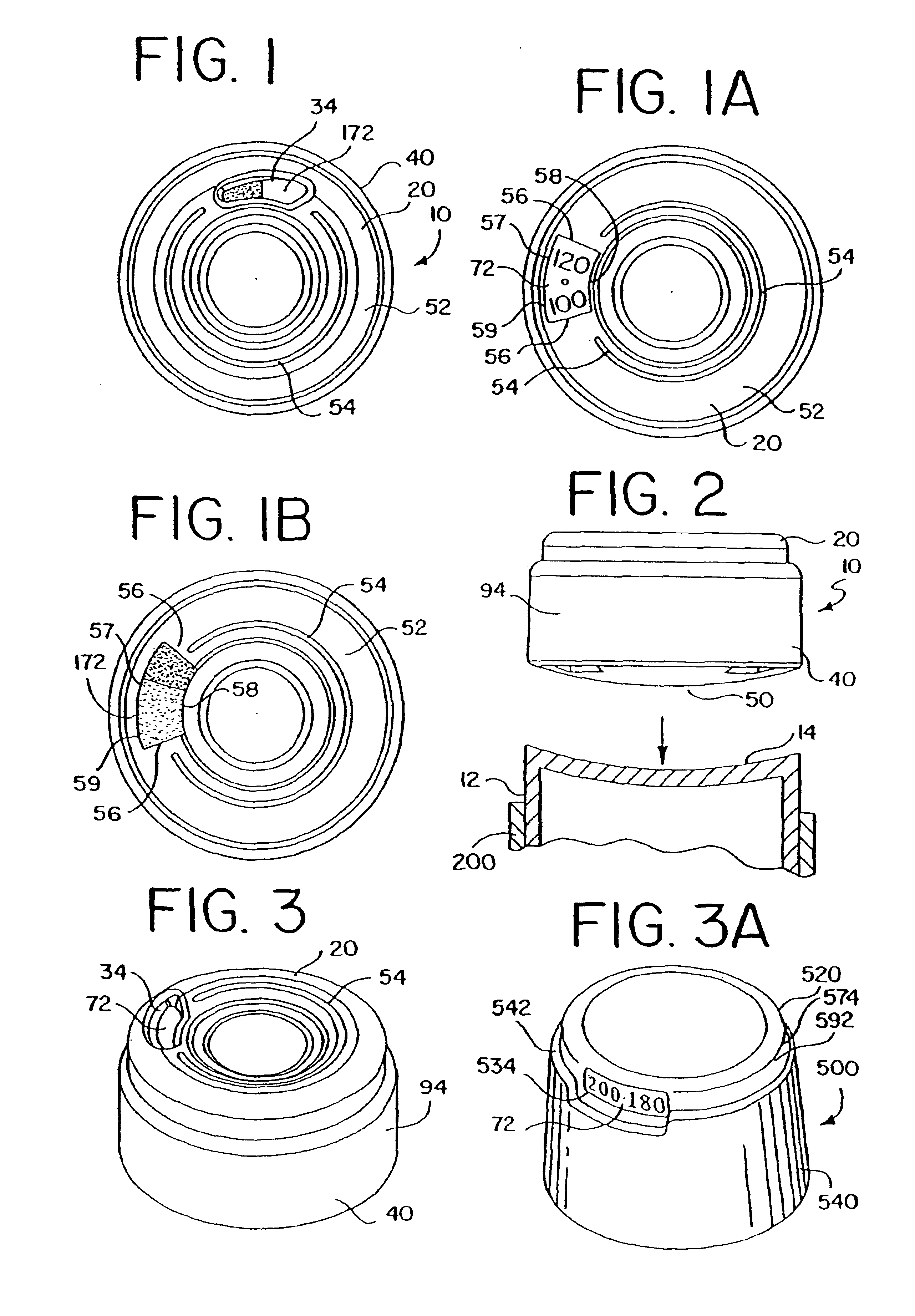
[0078]Referring to the drawings, and in particular FIGS. 31 and 32, an aerosol dispenser is shown as including a housing 200, or actuator boot, and a container 12 disposed therein. The housing has a longitudinally extending cavity 202 shaped to receive the container. A top portion of the housing is generally open such that the container can be inserted in the housing through opening 204 and be installed therein with a bottom end 14 of the container protruding from the housing so as to be exposed to the user for actuation.

[0079]The terms “longitudinal” and “axial” as used herein are intended to indicate the direction of the reciprocal movement of the container relative to the housing, and of an indicating device cap member relative to a base member. The terms “top,”“bottom,”“upwardly” and “downwardly” are intended to indicate directions when viewing the inhalation devices as shown in the Figures, but with the understanding that the container is inverted such that the top surface ther...


PUM


Abstract

An indicating device for indicating the number of dosages of a substance that have been dispensed from or remain in a container includes a first indicator member incrementally moveable to a plurality of positions and a second indicator member operably connected to the first indicator member. The second indicator member is moveable in response to a predetermined number of movements of the first indicator member. One of the first and second indicator members includes numerical indicia and the other thereof includes color indicia.

Description

[0001]This application is a continuation of application Ser. No. 10 / 409,247, filed Apr. 8, 2003, which is continuation of application Ser. No. 10 / 039,744, filed Oct. 26, 2001 now U.S. Pat. No. 6,761,161, which is a continuation of application Ser. No. 09 / 303,043, filed Apr. 30, 1999, now issued as U.S. Pat. No. 6,336,453, and which also is a continuation-in-part of application Ser. No. 09 / 603,427, filed Jun. 26, 2000, now issued as U.S. Pat. No. 6,328,037, which is a continuation of application Ser. No. 09 / 073,275, filed May 5, 1998, now issued as U.S. Pat. No. 6,082,358, the entire disclosures of which are hereby incorporated by reference.BACKGROUND OF THE INVENTION[0002]The present invention relates generally to an indicating device for indicating the number of metered dosages that have been dispensed from, or remain in, an aerosol container, and in particular, to an indicating device adapted to be mounted to the aerosol container.[0003]Aerosol dispensing devices have been develop...

Claims


Application Information

Patent Timeline
Patent Type & Authority Patents(United States)
IPC IPC(8): A61M15/00G06M1/28G06M1/00G06M1/04G06M1/08B65D83/40B67D7/22G06M3/00G06M7/00G09F11/00
CPCA61M15/0065A61M15/009G06M1/041A61M15/0075A61M15/002A61M15/0068A61M15/0073G06M1/283
Inventor SCARROTT, PETER MYCOLAGRYCHOWSKI, JERRY R.SCHMIDT, JAMES NICKFOLEY, MARTIN P.
Owner TRUDELL MEDICAL INT INC
Why Eureka
Try Eureka