Direct crankshaft of air compressor

a crankshaft and air compressor technology, applied in the direction of positive displacement liquid engines, piston pumps, hoisting equipment, etc., can solve the problems of technical limit of crankshaft, cannot achieve crankshaft, etc., and achieve excellent air cooling effect, cancellation of pressurizing and vacuuming phenomena, and compact structur

Inactive Publication Date: 2013-03-05
KOHANDS CO LTD
View PDF15 Cites 56 Cited by
  • Summary
  • Abstract
  • Description
  • Claims
  • Application Information

AI Technical Summary

Benefits of technology

[0014]As described above, according to the present invention, components such as the balance weight and the connecting member are eliminated and two crank plates are overlapped with each other to be integrated so that the direct crankshaft can be configured more compactly. Compression cylinders are arranged in the radial direction and top dead centers and bottom dead centers can be symmetrically arranged.
[0015]Thus, excellent air cooling effect can be guaranteed and the cancellation of the pressurizing and vacuuming phenomena can be obtained. Absolute load positions are symmetrically arranged so that the motor can be more smoothly driven.
[0016]Moreover, the direct crankshaft is directly connected to the motor so that various driving components such as belt pulleys, a belt, a safety net, a bearing, etc. can be eliminated, due to this, manufacturing costs can be reduced, and economic advantages can be enhanced.

Problems solved by technology

In other words, a crankshaft having all the advantages of the single-pin crankshaft, the dual-pin crankshaft, and the pinless crankshaft cannot be accomplished by the present technology, because the usual crankshaft has technical limit in employing the connecting member to connect the rod coupling units with each other and the balance weight to maintain the balance during the rotation.

Method used


Image

  • Direct crankshaft of air compressor
  • Direct crankshaft of air compressor
  • Direct crankshaft of air compressor

Examples


Embodiment Construction

[0036]These and / or other aspects and advantages of the present invention will become apparent and more readily appreciated from the following description of the embodiments. Hereinafter, embodiments of the present invention will be described in detail with reference to the accompanying drawings.

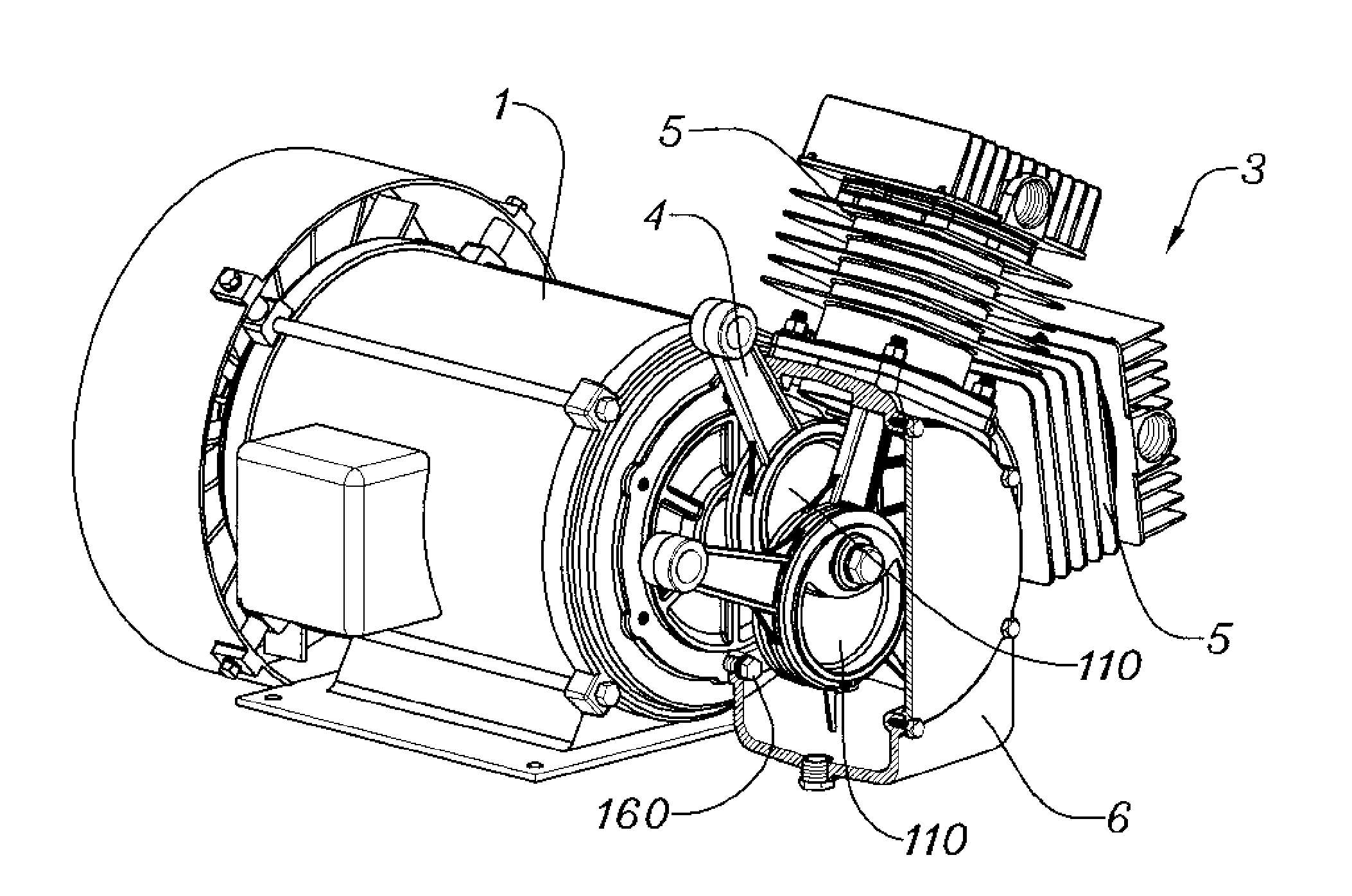
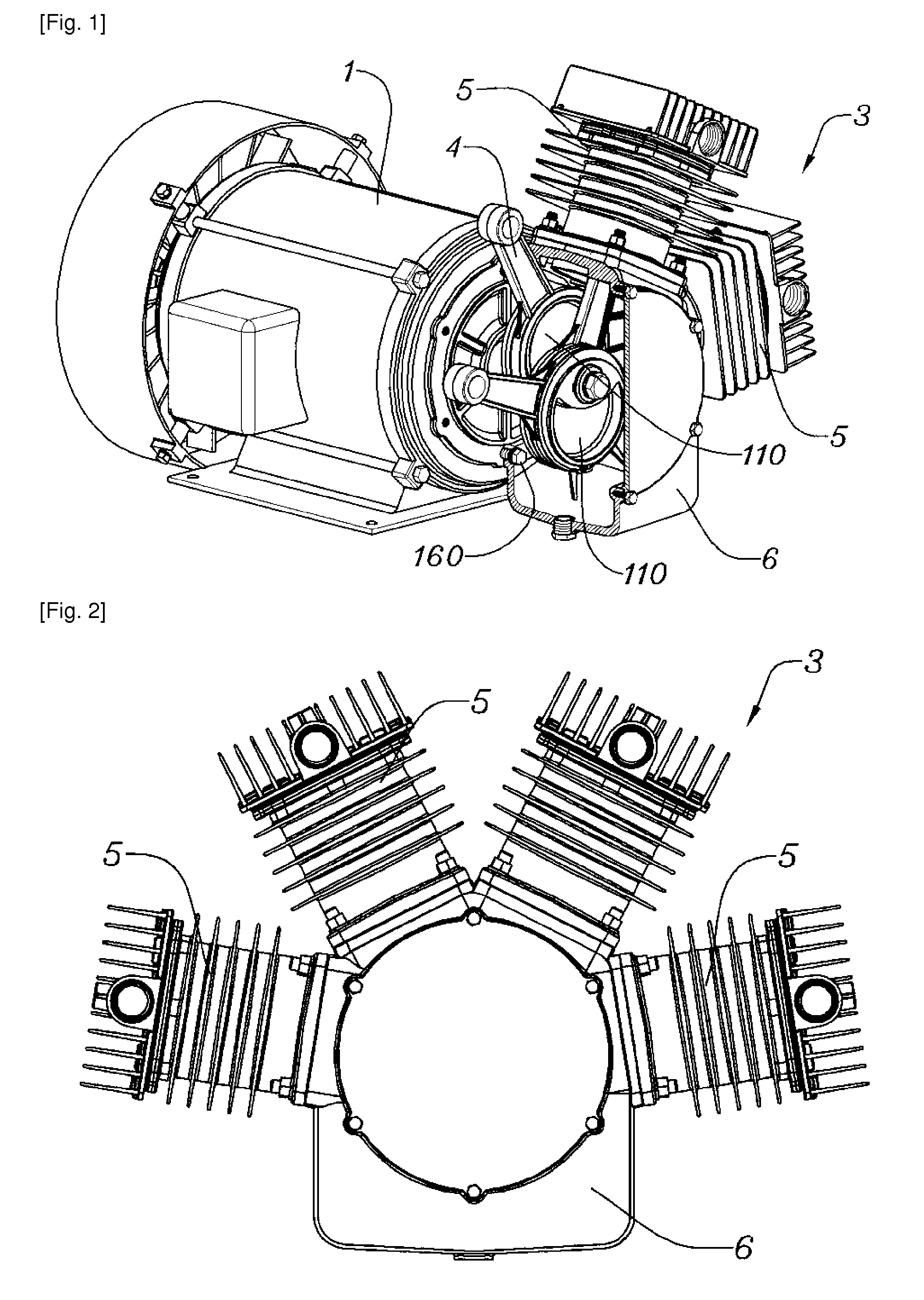
[0037]In the present invention, a compact direct crankshaft, in which a conventional standard crankshaft employed in a piston type air compressor is excluded and a balance weight and a connecting member to connect rod coupling units with each other are eliminated, is directly installed to a motor so that all individual advantages of conventional crankshafts can exhibit.

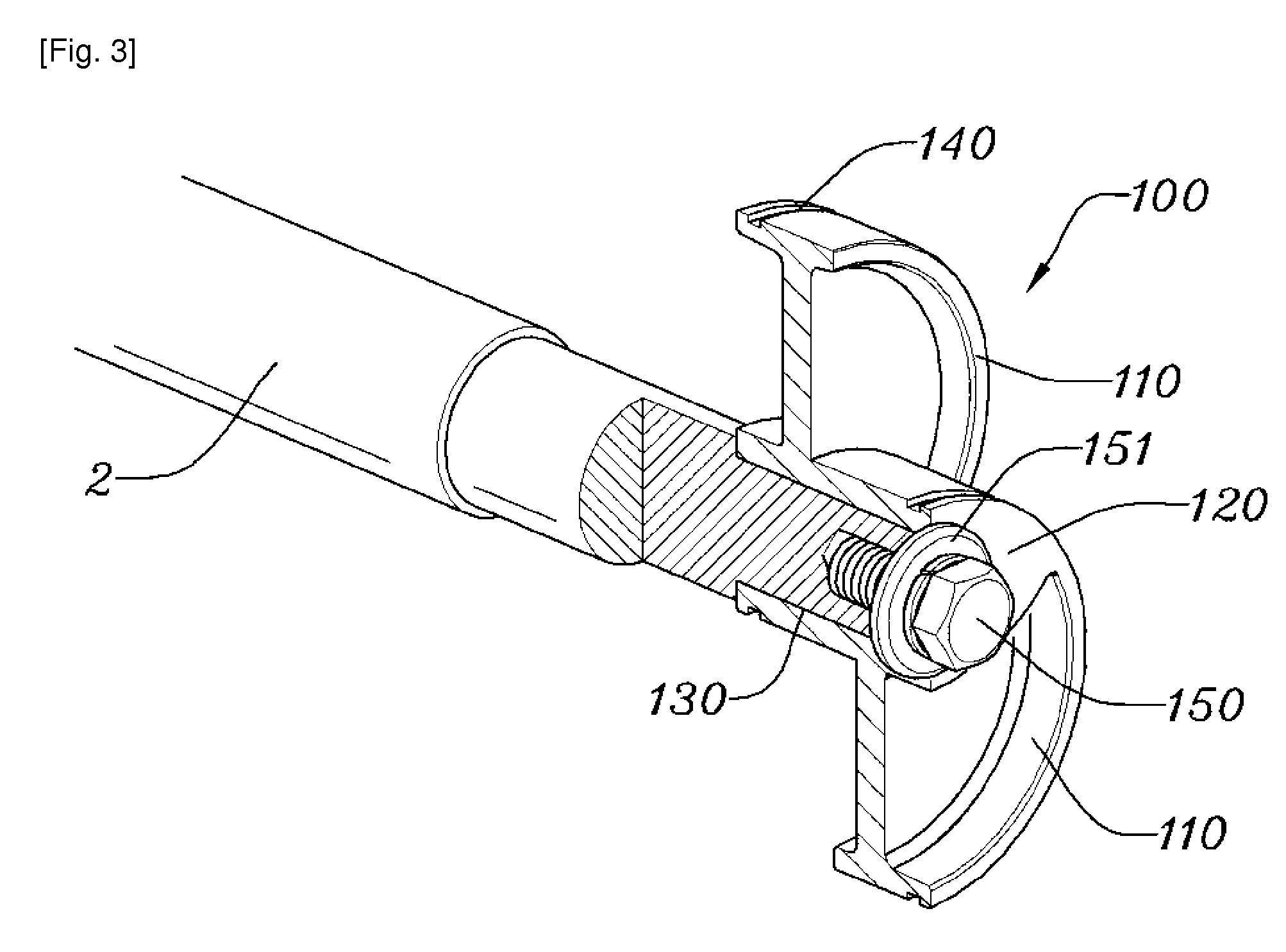
[0038]In order to achieve the aspect of the present invention, as illustrated in FIGS. 3 and 4, a direct crankshaft according to an embodiment of the present invention is implemented by which a plurality of crank plates 110 are integrated with each other to form an overlapping unit 120 and the overlapping unit 120 has a shaft c...


PUM


Abstract

There is provided a direct crankshaft of an air compressor for producing compressed air in which a crankshaft is implemented by two crank plates integrally overlapped with each other so that compression cylinders can be arranged in the radial direction to exhibit an excellent air cooling performance, top dead centers and bottom dead centers of the compression cylinders are symmetrically arranged so that the cancellation between pressurizing and vacuuming phenomena and the running of a motor can be smoothly performed, and the motor is integrated with a compression pump so that various driving components such as belts, pulleys, covers, and the like are eliminated and manufacturing costs are remarkably reduced. The direct crankshaft includes crank plates integrated with each other to form an overlapping unit. The overlapping unit has a shaft coupling hole through which a motor shaft penetrates such that the direct crankshaft is directly coupled with a motor.

Description

RELATED APPLICATIONS[0001]This application is a 371 application of International Application No. PCT / KR2007 / 003144, filed Jun. 28, 2007, which in turn claims priority from Korean Patent Application No. 10-2006-0117690, filed Nov. 27, 2006, both of which are incorporated herein by reference.TECHNICAL FIELD[0002]The present invention relates to an air compressor for producing compressed air, and more particularly, to a direct crankshaft of an air compressor in which a crankshaft is implemented by two crank plates integrally overlapped with each other so that compression cylinders can be arranged in the radial direction to exhibit an excellent air cooling performance, top dead centers and bottom dead centers of the compression cylinders are symmetrically arranged so that the cancellation between pressurizing and vacuuming phenomena and the running of a motor can be smoothly performed, and the motor is integrated with a compression pump so that various driving components such as belts, ...

Claims


Application Information

Patent Timeline
Patent Type & Authority Patents(United States)
IPC IPC(8): F04B1/04
CPCF04B27/0414F04B39/0094Y10T74/19916F04B1/04F04B1/02
Inventor SUNG, JOO-HWAN
Owner KOHANDS CO LTD
Why Eureka
Try Eureka