Microscope

a microscope and microscope technology, applied in the field of microscopes, can solve the problems of difficult to distinguish the boundary between the background and the sample, and achieve the effect of compact structur

Inactive Publication Date: 2010-06-10
ALTAIR CORP
View PDF0 Cites 2 Cited by
  • Summary
  • Abstract
  • Description
  • Claims
  • Application Information

AI Technical Summary

Benefits of technology

[0019]The microscope can thereby be configured more compactly than in a case where the light projector is arranged on the opposite side of the placement portion in relation to the pattern body in order to illuminate the sample. In addition, the sample can be observed with easily- viewable brightness by varying how the light is applied to the sample.

Problems solved by technology

In a conventional microscope, when a transparent or semitransparent sample is observed while being illuminated from behind of the sample in relation to a lens barrel, it is difficult to distinguish a boundary between a background and the sample due to transparency of the sample (in other words, due to low-contrast), and it is thereby impossible to recognize the sample as shown in FIG. 10.

Method used


Image

  • Microscope
  • Microscope
  • Microscope

Examples


Embodiment Construction

[0033]Embodiments according to the present invention will be illustrated hereinafter by way of drawings.

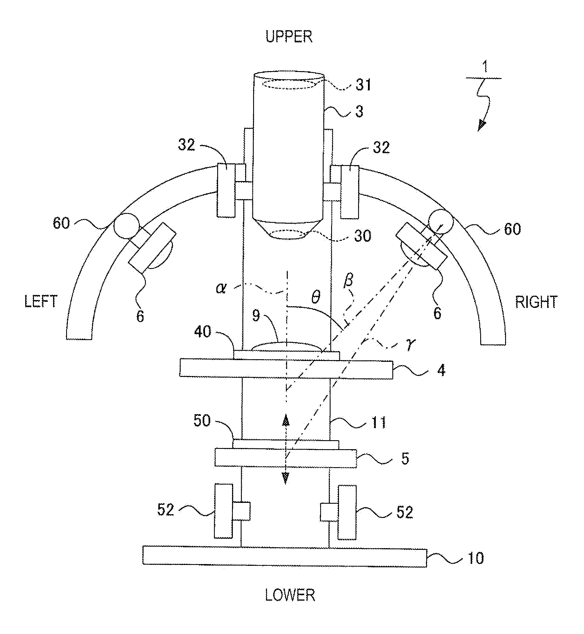
[0034]Hereat, FIG. 1 is a schematic diagram of a microscope according to the present embodiment viewed from a front side.

[0035]In explanations hereinafter, an upper side, a lower side, a right side, and a left side relative to a direction of gravitational force when a microscope 1 is viewed from the front side is respectively referred to as an upper side, a lower side, a right side, and a left side. FIG. 1 is the diagram of the microscope 1 viewed from the front side, and on the sheet, an upper side, a lower side, a right side, and a left side of the sheet respectively correspond to the upper side, the lower side, the right side, and the left side, as indicated on the sheet.

1. Overall structure

[0036]As shown in FIG. 1, the microscope 1 according to the present embodiment includes a base 10 which is placed on the not-shown placement surface, and a support post 11 which is provided ...


PUM


Abstract

A microscope with which a transparent or semitransparent sample can be stereoscopically observed is provided. The microscope includes a placement portion for placing the sample thereon, a magnifier for magnifying the sample to a size viewable through an objective lens, a pattern body where a pattern has been drawn, and a light projector for applying light to at least the pattern body. The placement portion, the pattern body, and the light projector are arranged at positions which enable light projected from the light projector to be applied through the pattern body to the sample arranged within a depth of field of the magnifier by the placement portion.

Description

TECHNICAL FIELD[0001]This invention relates to a microscope.BACKGROUND ART[0002]In a conventional microscope, when a transparent or semitransparent sample is observed while being illuminated from behind of the sample in relation to a lens barrel, it is difficult to distinguish a boundary between a background and the sample due to transparency of the sample (in other words, due to low-contrast), and it is thereby impossible to recognize the sample as shown in FIG. 10.[0003]Therefore, in a dark-field microscope, for example, a sample is illuminated obliquely to an optical axis, and light is thereby scattered or reflected on the sample. As a result, the sample is brightened in contrast to a background, which provides higher contrast. Alternatively, in phase-contrast microscope, phase difference is converted into contrast between light and dark through a condenser, whereby difference in refractive index is clarified and a sample becomes recognizable. Furthermore, in a differential inter...

Claims


Application Information

Patent Timeline
Patent Type & Authority Applications(United States)
IPC IPC(8): G02B21/06
CPCG02B21/06G02B21/22G02B21/12G02B21/086
Inventor HIRAFUJI, MAMORUTOMINAGA, ICHIROEDA, SHIGETO
Owner ALTAIR CORP
Why Eureka
Try Eureka