Membrane Pump

a membrane pump and membrane technology, applied in the field of electromagnetic driven membrane pumps, can solve the problems of insufficient power given off by electromagnets, insufficient uniformity of uniform plates, and insufficient elastic uniform plates

Active Publication Date: 2009-07-02
XAVITECH AB
View PDF10 Cites 64 Cited by
  • Summary
  • Abstract
  • Description
  • Claims
  • Application Information

AI Technical Summary

Problems solved by technology

The problem with using a uniform spring in small membrane pumps is that the power given off by the electromagnets is so small that the spring steel plate would have to be very thin for the membrane pump to function.
Another problem arises during the use of a uniform flat spring in a small membrane pump.
The problem is that a uniform plate is essentially elastic in the center of the spring when power is applied there.
Therefore it is not possible to control the resiliency of the spring which causes major stress and wear and tear on the attachment.
This wear and tear may cause play which may greatly shorten the pu...

Method used


Image

  • Membrane Pump
  • Membrane Pump
  • Membrane Pump

Examples


first embodiment

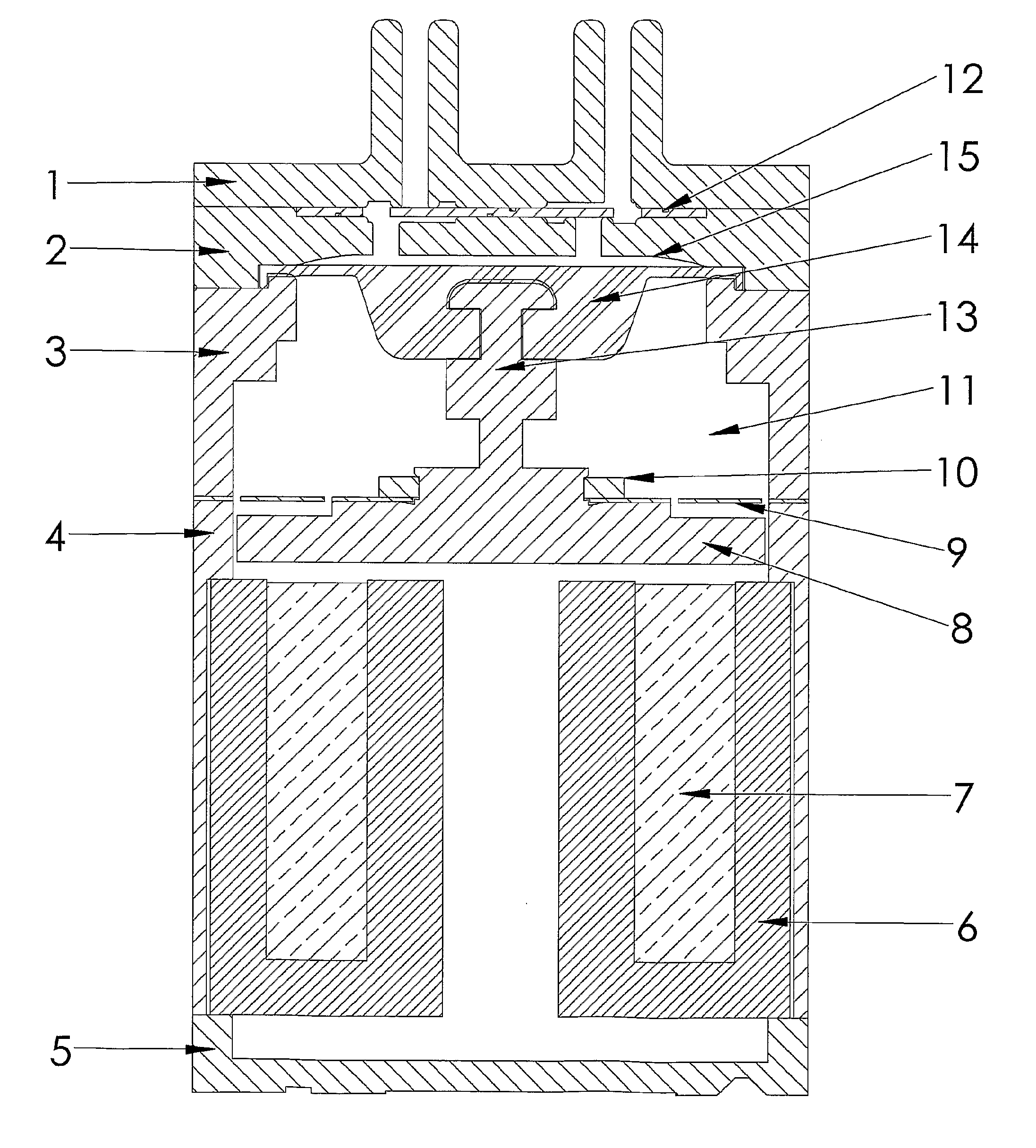
[0012]FIG. 1 shows in cross section an electromagnetic driven membrane pump optimized to emit negative pressure.

second embodiment

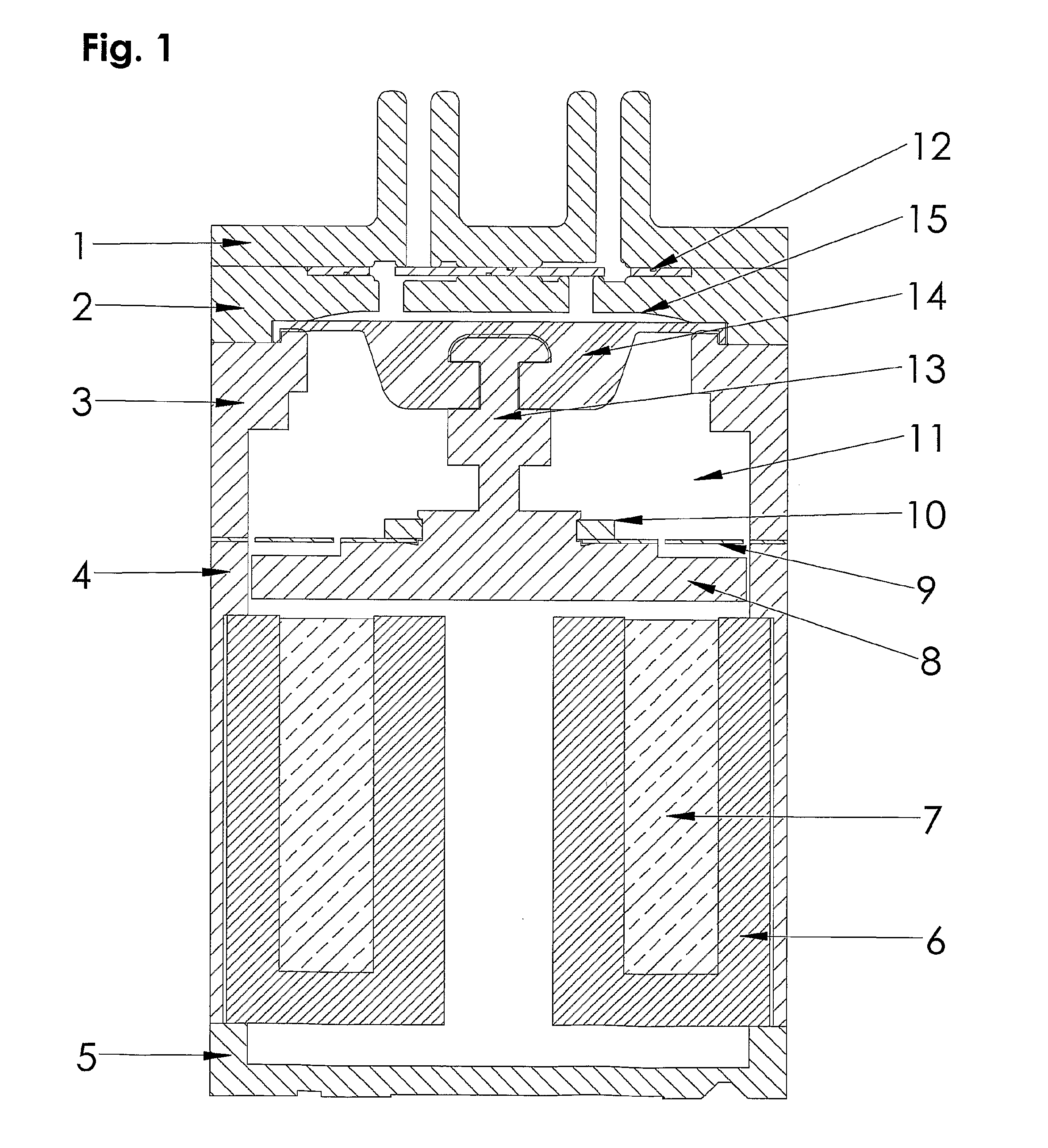
[0013]FIG. 2 shows in cross section an electromagnetic driven membrane pump optimized to emit positive pressure.

[0014]FIG. 3 shows a flat spring with four legs.

[0015]FIG. 4 shows a flat spring with three legs.

[0016]FIG. 5 shows a flat spring with two legs.

[0017]FIG. 6 shows a flat spring with six legs.

[0018]With reference to FIG. 1 the first preferred embodiment of an electromagnetic driven membrane pump optimized to emit negative pressure is shown. The membrane pump is comprised of a casing (enclosed covering) hereafter called the pump housing essentially comprised of a first gable 1, a flange 2, a first middle part 3, a second middle part 4 and a second gable 5. In the pump housing an inner space 11 is created which is separated by a membrane 14, which is connected to the pump housing's inner walls, thereby creating a space in the form of a pump chamber 15 between the membrane and the second flange. The connection of the membrane to the walls of the pump housing can preferably be ...


PUM


Abstract

An electromagnetic driven membrane pump has a pump housing inside which at least one pump chamber (15) having at least one intake and outlet is formed and delimited between a gable (1) of the pump housing and at least one completely-sealed membrane (14) attached to a wall (4) of the pump housing and, in an axial direction of the pump housing, to a running axle (13) suspended in at least two separated suspensions in a longitudinal direction of the axle (13). At least one of the suspensions is composed of a flat spring (9) attached to the axle (13) in a radial direction out toward the wall (4) of the pump housing. The axle (13) is composed of magnetic material to be driven by a magnetic field from an electromagnet (7) for oscillation in its longitudinal direction and moving the membrane (14) in corresponding oscillating movement. The flat spring (9) is composed of an inner and at least one outer part, with the inner part attached to the axle (13) and the outer part(s) attached to the pump housing. These parts are connected with one another by two elastic legs, arranged at each side of the point where the spring is attached to the axle (13).

Description

TECHNICAL FIELD[0001]The present invention concerns an electromagnetic driven membrane pump. More specifically, the invention relates to an electromagnetic driven membrane pump in accordance with the claims.TECHNICAL BACKGROUND[0002]Membrane pumps that apply pressure or negative pressure are found in a large variety of variations and sizes and are used in many different applications, everything from large industrial membrane pumps to very small membrane pumps for medical purposes. A significant problem during the development of small membrane pumps is that it is difficult to construct a membrane pump that combines a cost efficient method of production with a long lifespan and a high performance level.[0003]The most common type of membrane pump that exists is driven by a rotating motor, which with the aid of an eccentric causes a membrane to perform an oscillating pumping motion. An advantage of powering a membrane pump with an electric motor is that the diameter of the rotor can be ...

Claims


Application Information

Patent Timeline
IPC IPC(8): F04B45/047F04B17/03F04B43/04
CPCF04B35/045H02K33/02F04B45/047F04B43/04F04B53/16F04B53/10F05B2210/12Y10S417/00F04B17/044H02K33/00
Inventor STENBERG, JOHAN
Owner XAVITECH AB
Why Eureka
Try Eureka