Energy conversion cells using tapered waveguide spectral splitters

a technology of energy conversion cells and spectral splitters, which is applied in the field of cells, can solve the problems of affecting the efficiency of energy conversion cells, and requiring kinetic energy for machines, etc., and achieves the effects of easy manufacturing, increased energy efficiency of radiant energy conversion cells, and low cos

Active Publication Date: 2015-08-20
WERTSBERGER SHALOM
View PDF4 Cites 48 Cited by
  • Summary
  • Abstract
  • Description
  • Claims
  • Application Information

AI Technical Summary

Benefits of technology

[0038]It is therefore an object of the invention to provide a device and technology to increase the energy efficiency of a radiant energy conversion cells which is relatively inexpensive, easy to manufacture, and wh...

Problems solved by technology

However this type of machinery requires kinetic energy, largely derived from fossil fuel, which is expensive and carries an environmental cost.
Significant effort has been directed to higher utilization of solar energy but efficiency, space, and cost considerations hampered this effort to date.
Notably, Bragg mirrors are very frequency selective, complex to manufacture, and require at least a width higher than ¾ wavelength to provide any breadth of spectrum.
Furthermore, when certain metals are disposed at low thicknesses they tend to “ball-up” and form small “islands”.
Normal incidence has the limitation of a finite probability of detecting energy before it is transmitted through the collection layer.
Energy trans...

Method used


Image

  • Energy conversion cells using tapered waveguide spectral splitters
  • Energy conversion cells using tapered waveguide spectral splitters
  • Energy conversion cells using tapered waveguide spectral splitters

Examples


Embodiment Construction

[0071]Certain figures and embodiments of the invention will be described herein by way of example to increase the understanding of different aspects of the invention.

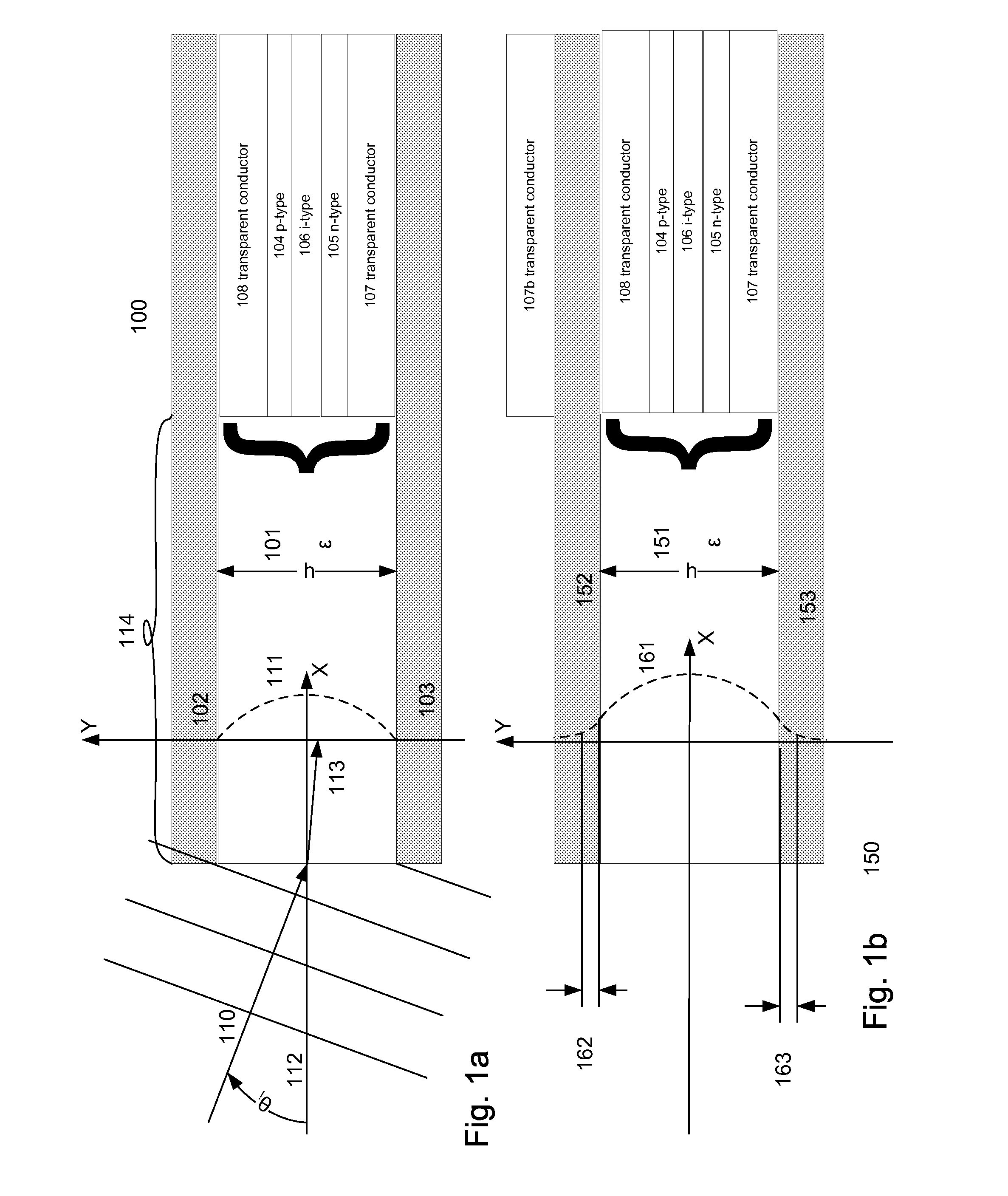
[0072]FIGS. 1a and 1b alternately depict a short region of waveguide with insignificant variation of thickness, and are provided for simple explanation of the propagation characteristics of radiant energy within such waveguides. For the purpose of explanation, FIGS. 1a and 1b may be considered to represent a cutout of a short region of the CRTR tapered core waveguide.

[0073]FIG. 1.a shows a two dimensional waveguide 100 comprising a waveguide core material 101 of thickness (width), h, formed between conductors 102 and 103. Optionally, the waveguide core material 101 could be replaced by a plurality of layers forming an aggregate optically equivalent to a uniform material having dielectric constant, E, and the same overall thickness. Such construction would be recognized as equivalent by the skilled artisan. In plurality ...


PUM


Abstract

An energy converter for converting multi-frequency radiant energy into electrical energy is disclosed, comprising a plurality of superposed lateral waveguides having photovoltaic energy transducers disposed within. The waveguide include charge collectors, which may be the cladding. A plurality of spectral refractors termed Continuous Resonant Trap Refractors (CRTR) are disposed within the lateral waveguides the refractors comprising a tapered core waveguide, the wider end of which defining an aperture, and the tapered core width decreasing in magnitude as a function of the depth. A cladding is disposed about the tapered core. The aperture of the tapered core is dimensioned to allow passage of radiant energy comprising at least two frequencies. The varying width of the tapered core will cause different frequencies to reach a state at which they will penetrate the cladding and be emitted from the spectral refractor sorted by depth, and be coupled to respective lateral waveguides and/or transducers.

Description

RELATED APPLICATIONS[0001]Aspects of the present invention were first disclosed in U.S. Patent Application 61 / 701,687 to Andle and Wertsberger, entitled “Continuous Resonant Trap Refractor, Waveguide Based Energy Transducers, Energy Conversion Cells, and Display Panels Using Same”, filed 16 Sep. 2012. Further refinements of the tapered waveguide based Continuous Resonant Trap Refractor (CRTR) and to lateral waveguides with which CRTRs may cooperate, were disclosed together with various practical applications thereof in the following additional U.S. Patent Applications: 61 / 713,602, entitled “Image Array Sensor”, filed 14 Oct. 2012; 61 / 718,181, entitled “Nano-Scale Continuous Resonance Trap Refractor”, filed 24 Oct. 2012; 61 / 723,832, entitled “Pixel Structure Using Tapered Light Waveguides, Displays, Display Panels, and Devices Using Same”, filed 8 Nov. 2012; 61 / 723,773, entitled “Optical Structure for Banknote Authentication”, filed 7 Nov. 2012; Ser. No. 13 / 726,044 entitled “Pixel St...

Claims


Application Information

Patent Timeline
IPC IPC(8): G02B6/122H02M3/07G02B6/42H01L31/0232
CPCG02B6/1228G02B6/42H02M3/07H01L31/02327G02B6/12002G02B6/12007G02B6/4298H01L27/14629H01L31/054H01L31/0549Y02E10/52Y02E10/56
Inventor ANDLE, JEFFREY C.WERTSBERGER, SHALOM
Owner WERTSBERGER SHALOM
Why Eureka
Try Eureka