Drive roller control for toric-drive transmission

a technology of toric-drive transmission and drive roller, which is applied in the direction of friction gearing, belt/chain/gearing, gearing element, etc., can solve the problems of reducing the amount of force required to actuate the change in the input-to-output ratio, the internal combustion engine will not run below the minimum revolution per minute (rpm), and the detriment of the vehicle speed. , to achieve the effect of reducing the amount of force required to actuate th

Active Publication Date: 2007-05-15
S O E TECH
View PDF6 Cites 151 Cited by
  • Summary
  • Abstract
  • Description
  • Claims
  • Application Information

AI Technical Summary

Benefits of technology

[0007]It is a further feature of the present invention to provide a continuously variable transmission having an increased energy efficiency.
[0008]It is a still further feature of the present invention to provide a continuously variable transmission in which the amount of force required to actuate a change in input-to-output ratio is reduced.

Problems solved by technology

An internal combustion engine, on the other hand, will not run below a minimal revolutions per minute (RPM) and is also limited with respect to the maximal RPM it may attain.
Furthermore, the transmission must allow ratio changes between the engine output and the propelling system input, as high torque is typically required initially to propel the idle vehicle forward, to the detriment of the vehicle speed.
On the other hand, the discontinuity between the speed ratios and the necessity for clutching to switch speeds are major inconveniences.
There is a loss in engine power, although small, when switching from one ratio to another.
These transmissions also are more complex and require synchronization between the ratio changes.
However, CVT's are typically less energy-efficient than discontinuous ratio transmissions.

Method used


Image

  • Drive roller control for toric-drive transmission
  • Drive roller control for toric-drive transmission
  • Drive roller control for toric-drive transmission

Examples


Embodiment Construction

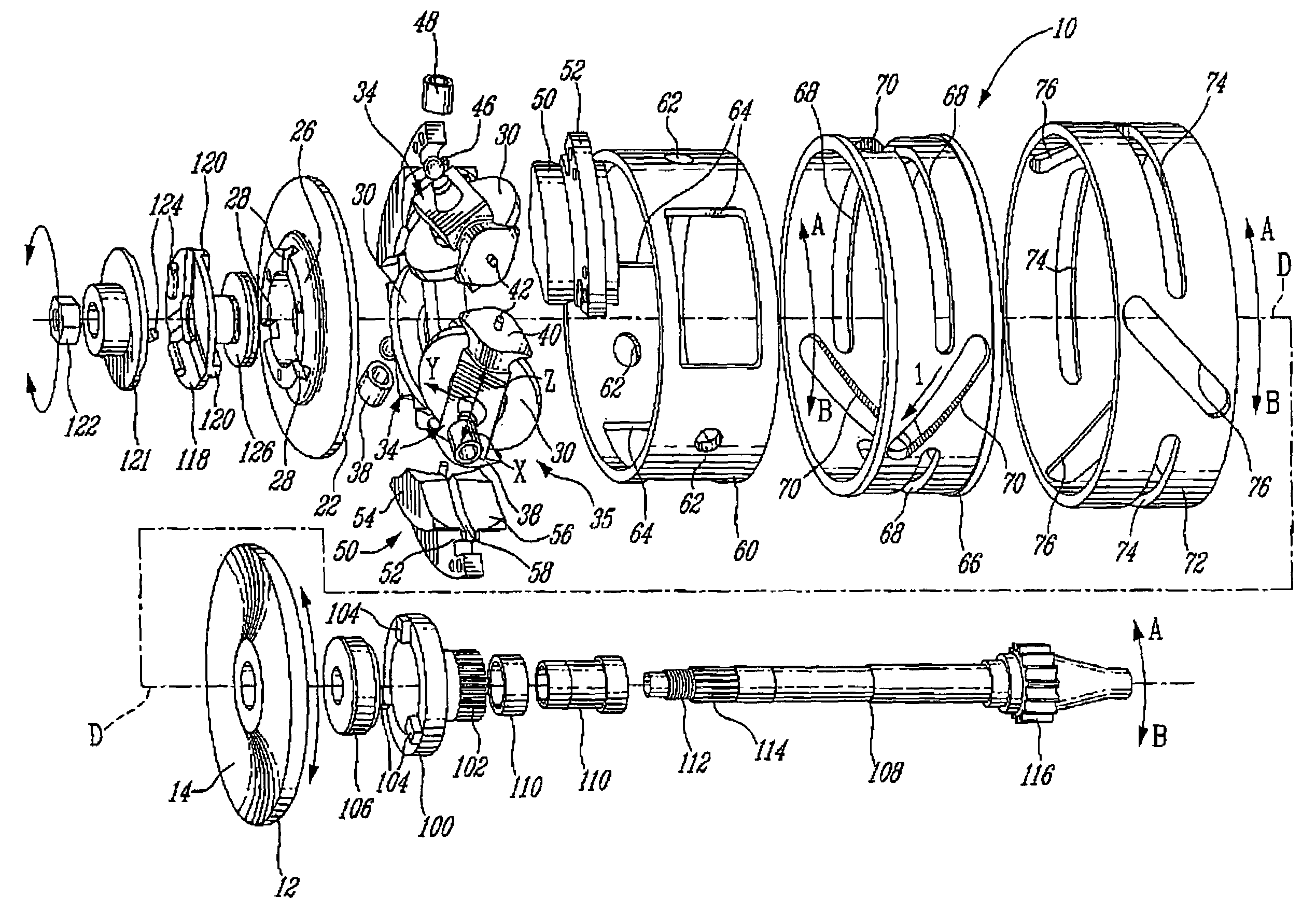
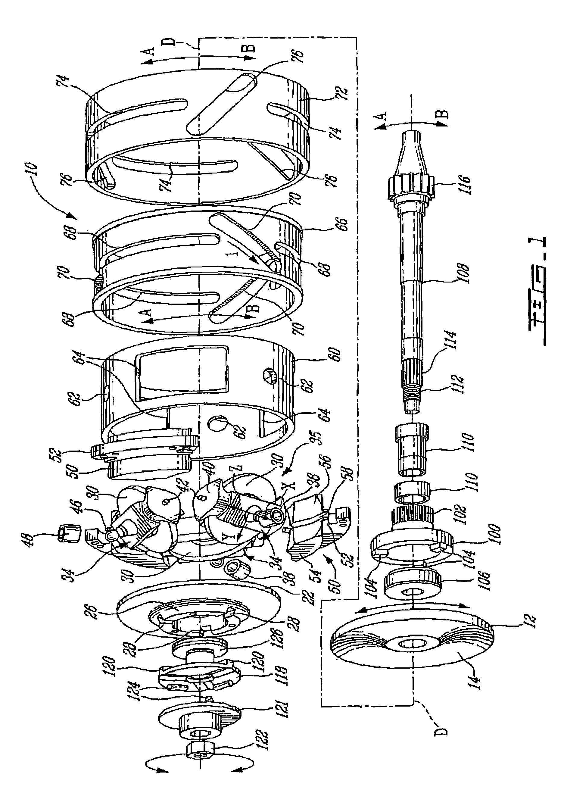
[0019]Referring now to the drawings and more particularly to FIG. 1, a toric-drive transmission in accordance with the present invention is generally shown at 10. A protective casing, along with the necessary seals and joints, has been removed from the figures in order to clarify the views of the transmission 10. The toric-drive transmission 10 of the present invention is protected from dust and water, as it is enclosed in the casing (not shown). The various elements of the transmission 10 are shown exploded. A drive axis is generally shown at D.

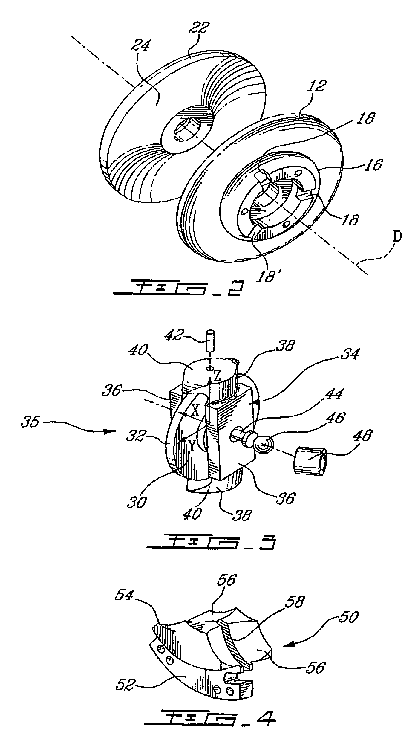
[0020]The transmission 10 comprises a drive disk 12. As seen in FIGS. 1, 2 and 5A to 5C, the drive disk 12 has a groove 14 which is a portion of a torus. The drive disk 12 has on an opposed side a flange 16 (FIG. 2) extending axially with three connection slots 18 therein. A driven disk 22 is a mirror image of the drive disk 12. The driven disk 22, therefore, also has a groove 24 which is a portion of a torus, and on an opposed side a flange...


PUM


Abstract

A toric-drive transmission comprising a drive disk for receiving a power input. A driven disk transmits a power output. A roller device has a roller displaceably mounted between the drive disk and the driven disk. The roller has three rotational degrees of freedom. A first degree of freedom transmits motion from the drive disk to the driven disk to convert the power input to the power output. A second degree of freedom varies a ratio of the power output to the power input as a function of an orientation of the roller along the second degree of freedom. A third degree of freedom initiates a rotation of the roller about the second degree of freedom. A controller system is operatively connected to the roller device for changing the orientation of the roller in the second degree of freedom by actuating a displacement of the roller in the third degree of freedom.

Description

TECHNICAL FIELD[0001]The present invention generally relates to a toric-drive continuously variable transmission and, more particularly, to a drive roller control for use therewith.BACKGROUND ART[0002]Transmissions are used in motorized vehicles to transmit the engine power to the propelling system of the vehicles (i.e., wheels, propellers, etc.). Various types of transmissions adapt to the different engines and motors in order to propel the vehicle. An internal combustion engine, for instance, does not behave like an electric motor. An electric motor evolves between a full stop to high running speeds at high efficiencies. Therefore, a transmission may couple the electric motor directly to the propelling system. An internal combustion engine, on the other hand, will not run below a minimal revolutions per minute (RPM) and is also limited with respect to the maximal RPM it may attain. Therefore, the transmission used with such engines requires a clutching mechanism in order to allow ...

Claims


Application Information

Patent Timeline
Patent Type & Authority Patents(United States)
IPC IPC(8): F16H15/38F16H61/664
CPCF16H15/38F16H61/6648
Inventor CAREAU, FERNANDMALTAIS, HUGUES
Owner S O E TECH
Why Eureka
Try Eureka