Exhaust aftertreatment system using urea water

a technology of exhaust gas and aftertreatment system, which is applied in the direction of machines/engines, separation processes, lighting and heating apparatus, etc., can solve the problems of increasing the oxygen density of the exhaust gas, increasing the pressure loss, and causing energy loss, so as to prevent the deposition of urea water and reduce the reaction

Inactive Publication Date: 2007-02-15
HITACHI HIGH-TECH CORP +2
View PDF7 Cites 150 Cited by
  • Summary
  • Abstract
  • Description
  • Claims
  • Application Information

AI Technical Summary

Benefits of technology

[0021] According to the present invention, when the injected urea water is impinged against the plate, such as the porous plate or the flat plate, disposed in the exhaust gas, spray impingement flux of the urea water at the plate surface is decreased to cause film boiling upon the impingement of the urea water droplets against the plate, thereby preventing deposition of the urea water. Further, since the urea water reflected by the plate is uniformly dispersed into the exhaust gas, reduction reaction can be sufficiently developed by the denitration catalyst.
[0022] Also, since the plate, such as the porous plate, the flat plate, or a semi-cylindrical plate, is disposed in the exhaust gas, it is possible to prevent urea from being precipitated on the inner wall surface of the exhaust duct against which the spray injected from the urea water impinges if the plate is not disposed.

Problems solved by technology

However, that known technique has drawbacks that, because of supplying air into the exhaust gas, the oxygen density in the exhaust gas is increased, which is contradictory to the aim of promoting the reduction reaction of NOx, and that an energy loss is caused with consumption of the compressed air.
Thus, a first problem to be overcome in the exhaust aftertreatment system is to atomize the spray of the urea water without using the compressed air.
However, such a solution tends to increase a pressure loss as mixing of the urea water is promoted.

Method used


Image

  • Exhaust aftertreatment system using urea water
  • Exhaust aftertreatment system using urea water
  • Exhaust aftertreatment system using urea water

Examples


first embodiment

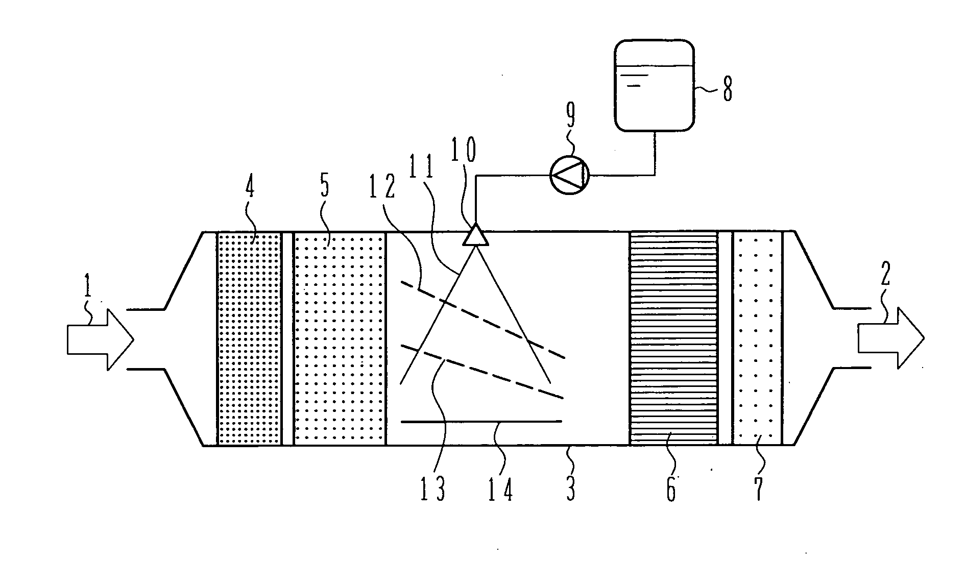
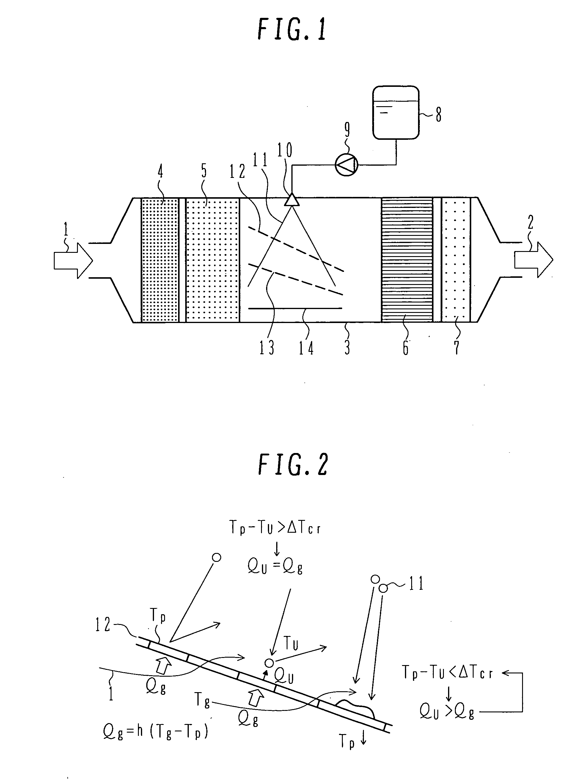
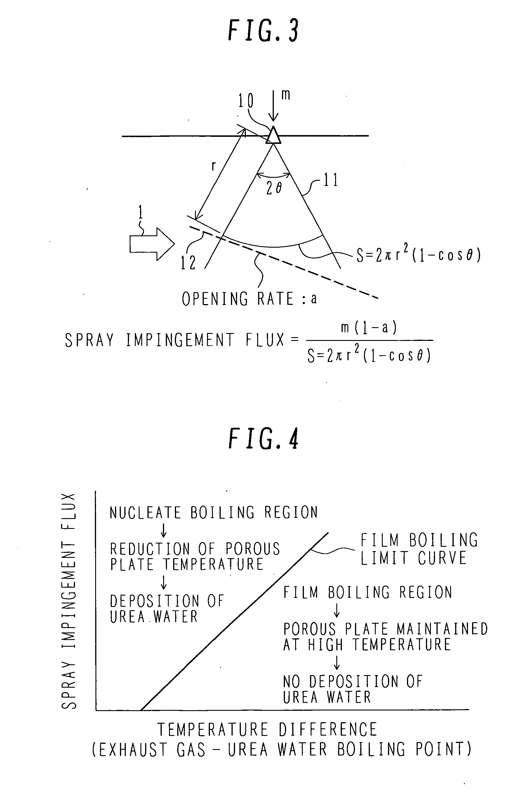
[0039] The exhaust aftertreatment systems according to the first embodiment of the present invention will be described below with reference to FIGS. 1-4. FIG. 1 is a schematic view showing the overall construction of the exhaust aftertreatment system according to the first embodiment of the present invention. FIG. 2 is an illustration for explaining a mechanism for preventing deposition of droplets of urea water when the urea water droplets impinge against a porous plate disposed in an exhaust duct in this embodiment. FIG. 3 is an illustration for explaining spray impingement flux of urea water spray, which is decided depending on the positional relationship between a urea water injector and the porous plate in this embodiment. FIG. 4 is a graph for explaining, based on the relationship between the spray impingement flux and the temperature of exhaust gas, phenomena occurred when the urea water spray impinges against the porous plate in this embodiment.

[0040] In the overall constru...

second embodiment

[0085]FIG. 5 is a schematic view showing the construction of a urea water dosing section in an exhaust aftertreatment system according to a second embodiment of the present invention. Components and members having the same functions as those in the first embodiment are denoted by the same reference numerals, and a description thereof is omitted here. Since the structures upstream of the filter 5 and downstream of the denitration catalyst 6 are the same as those in the first embodiment, those structures are omitted in FIG. 5.

[0086] In the second embodiment, the direction of injection from a urea water injector 21 is inclined toward the downstream side away from the vertical direction with respect to the flow of the exhaust gas. Such an arrangement can decrease a part of a spray 22 formed by the injection, which reaches the upstream side of the injection point with respect to the flow of the exhaust gas, and can prevent the spray from splashing the filter 5 even when the distance bet...

third embodiment

[0088]FIG. 6 is a schematic view showing the construction of a urea water dosing section in an exhaust aftertreatment system according to a third embodiment of the present invention. Components and members having the same functions as those in the first embodiment are denoted by the same reference numerals, and a description thereof is omitted here. Since the structures upstream of the filter 5 and downstream of the denitration catalyst 6 are the same as those in the first embodiment, those structures are omitted in FIG. 6.

[0089] In the third embodiment, the direction of injection from a urea water injector 30 is inclined toward the upstream side away from the vertical direction with respect to the flow of the exhaust gas. Plates 37, 38, 39 and 40 are arranged for impingement of a spray 36 injected from the injector 30, to thereby prevent the spray 36 from reaching the filter 5 disposed in the upstream side. Also, a plate 14 is disposed to prevent the spray 35 from depositing on th...


PUM

PropertyMeasurementUnit
molar ratioaaaaaaaaaa
unit timeaaaaaaaaaa

Abstract

An exhaust aftertreatment system comprises an injector for injecting urea water into an exhaust duct, and a denitration catalyst disposed downstream of the injector with respect to a flow of exhaust gas. The exhaust aftertreatment system reduces nitrogen oxides in the exhaust gas by the denitration catalyst while using ammonia produced from the urea water injected from the injector. The urea water is injected along a direction of the flow of the exhaust gas within the exhaust duct, and a porous plate is disposed in multiple stages in a space of the exhaust duct such that droplets of the injected urea water impinge against the porous plate before reaching a wall surface of the exhaust duct. A surface of the porous plate subjected to the impingement of the droplets is arranged to face downstream with respect to the flow of the exhaust gas. Deposition of the urea water is prevented by causing film boiling when the droplets impinge against the porous plate, and the urea water reflected by the porous plate is uniformly dispersed into the exhaust gas. Thus, the urea water is uniformly dispersed into the exhaust gas without increasing a pressure loss of the exhaust gas. The urea water is prevented from depositing on the wall surface and producing a precipitate in the form of a solid.

Description

BACKGROUND OF THE INVENTION [0001] 1. Field of the Invention [0002] The present invention relates to an exhaust aftertreatment system for an engine, and more particularly to an exhaust aftertreatment system which can efficiently remove nitrogen oxides in exhaust gas by using urea water as a reductant (reducing agent). [0003] 2. Description of the Related Art [0004] In a diesel engine, it has hitherto been proposed to install, midway an exhaust pipe through which exhaust gas flows, a selective reduction catalyst having a property of selectively reacting nitrogen oxides (hereinafter abbreviated to “NOx”) with a reductant even in the presence of oxygen. A required amount of reductant (e.g., hydrocarbon, ammonia or a precursor thereof) is dosed upstream of the selective reduction catalyst to develop reaction of the reductant with NOx in the exhaust gas, thereby suppressing the density of exhausted NOx. [0005] Such a NOx reducting method using the selective reduction catalyst is called S...

Claims


Application Information

Patent Timeline
Patent Type & Authority Applications(United States)
IPC IPC(8): B01D53/34B01D50/00
CPCB01D53/90F01N13/0097B01D2251/2067B01F3/04049B01F5/0268B01F5/0473F01N3/035F01N3/106F01N3/108F01N3/2053F01N3/2066F01N2240/20F01N2240/40F01N2570/14F01N2610/02F01N2610/102F01N2610/1453Y02T10/24B01D53/9431Y02A50/20Y02T10/12B01F23/2132B01F25/25B01F25/3141
Inventor NISHIOKA, AKIRAAMOU, KIYOSHISUKEGAWA, YOSHIHIROKOWATARI, TAKEHIKOHAMADA, YASUNAGAHAMADA, IKUHISAMUKAI, TOSHIFUMITAGUCHI, YOSHINORIYOKOTA, HIROSHI
Owner HITACHI HIGH-TECH CORP
Why Eureka
Try Eureka