Optimized Control System For Cooling Systems

a control system and cooling system technology, applied in the field of climate control systems, can solve the problems of undesirable fluctuations in the temperature of conditioned offices and other spaces, waste of cooling system resources, etc., and achieve the effect of improving the energy efficiency of the overall cooling system

Active Publication Date: 2009-07-02
YARDI SYST
View PDF24 Cites 147 Cited by
  • Summary
  • Abstract
  • Description
  • Claims
  • Application Information

AI Technical Summary

Benefits of technology

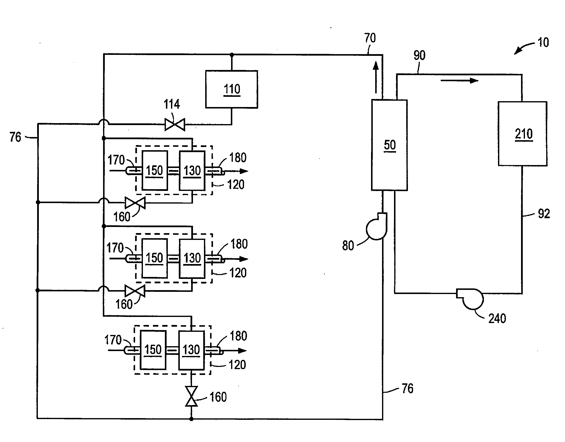
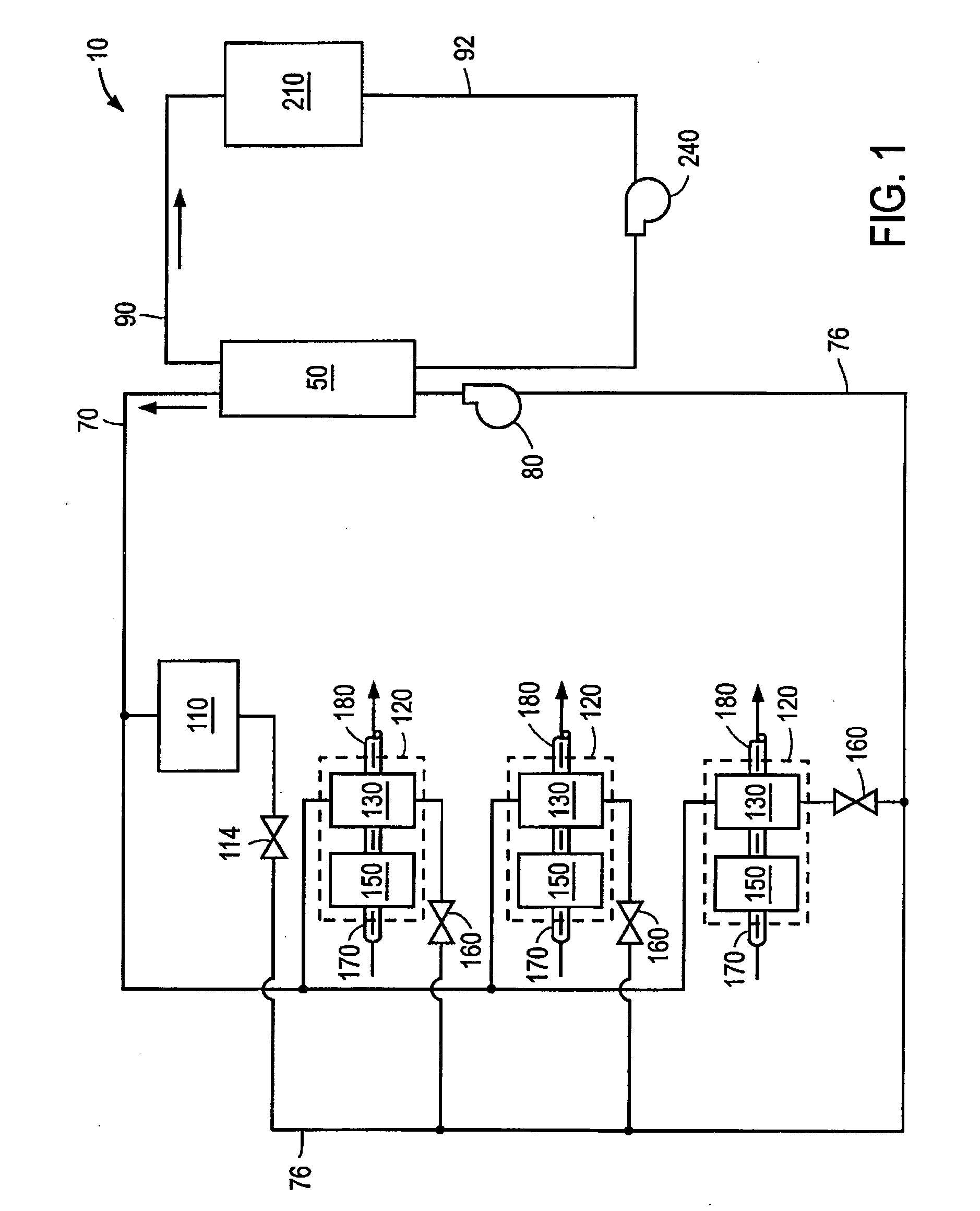
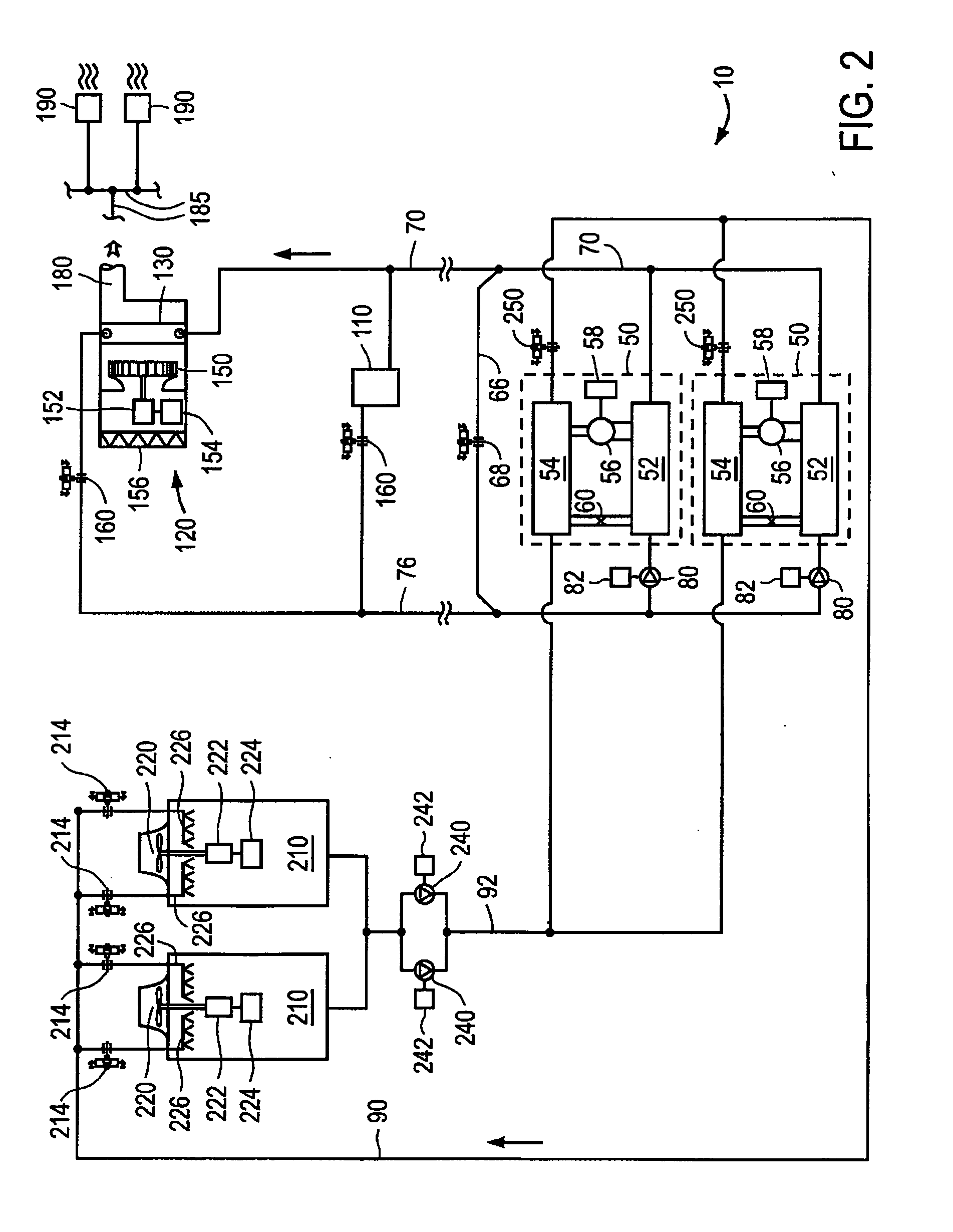
[0006]In one implementation, a control system for a cooling system incorporates control routines that are configured to detect actual end use cooling loads and adjust one or more operational setpoints to reduce energy consumption while desirably satisfying the cooling load demands.
[0008]In some implementations, the control system of the cooling system is configured to evaluate a cooling load value at the air handling unit or zone thermal unit and use the cooling load value to calculate at least one operational setpoint, which can be selected to improve the energy efficiency of the overall cooling system.

Problems solved by technology

If not properly controlled, such cooling systems can waste substantial amounts of energy.
In addition, improper control of such cooling systems results in undesirable fluctuations in the temperature of conditioned offices and other spaces within a facility and / or thermal variations in process loads.

Method used


Image

  • Optimized Control System For Cooling Systems
  • Optimized Control System For Cooling Systems
  • Optimized Control System For Cooling Systems

Examples


example

[0145]The following is one implementation of the detailed sequence steps that the control systems can use to reduce the overall energy costs of a cooling system.

[0146]Cooling Plant

[0147]I. Sequences

[0148]A. Integral Windup Prevention

[0149]1. Typical sequence for control loops: When the HVAC systems are shut down each night, and again when the systems are started up each morning, all integral terms in the controller are zeroed out so that there is no residual “integral windup” to interfere with normal system operation.

[0150]2. Similarly, when time delays are invoked that lock in a specific setpoint or speed, the tendencies of the control system will be to windup the integral term. When the time delay is released, the integral could drive the setpoint to one extreme or the other.

[0151]3. At the end of the time delay period, when the normal sequences are about to take over control of the variable, the integral term shall be zeroed out as required to maintain stable system operation.

[01...


PUM


Abstract

A cooling system for providing conditioned air to a facility includes a chiller or other cooling subsystem, a cooling tower subsystem and one or more air handling units or process cooling units. The cooling subsystem may advantageously include one or more chillers (e.g., variable speed chillers, constant speed chillers, absorption chillers, etc.) and chilled fluid pumps. The cooling tower subsystem includes one or more cooling tower units and condenser fluid pumps. In some implementations, the air handling unit has a cooling coil and a variable volume fan. In some implementations, direct expansion (DX) cooling systems comprise compressors, evaporators and air-cooled, water-cooled or evaporatively-cooled condensing systems. Such systems can be controlled to reduce energy waste, improve occupant comfort and / or improve the thermal characteristics of the process cooling unit. The cooling system further comprises a control system which is configured to evaluate a cooling load value at the air handling unit and use the cooling load value to calculate at least one operational setpoint. The operational setpoint may advantageously be selected to improve the energy efficiency of the overall cooling system.

Description

CROSS REFERENCE TO RELATED APPLICATION[0001]The present patent application claims priority under 35 U.S.C. §119 to U.S. Provisional Patent Application Ser. No. 60 / 876,754, filed on Dec. 22, 2006, and entitled, “OPTIMIZED CONTROL SYSTEM FOR COOLING SYSTEMS,” the entire disclosure of which is incorporated by reference herein.BACKGROUND[0002]1. Field of the Invention[0003]This application relates in general to the field of climate control systems, and in particular, to improved control systems and methods for operating cooling plants and distributed cooling systems.[0004]2. Description of the Related Art[0005]Cooling systems that utilize various system components to remove heat from an unconditioned or partially conditioned air stream or process load are common in medium and large buildings and other facilities. Such cooling systems typically include absorption, centrifugal, rotary screw or scroll water chillers, direct expansion (DX) based cooling systems, air handling units (AHUs), o...

Claims


Application Information

Patent Timeline
Patent Type & Authority Applications(United States)
IPC IPC(8): G05D23/00F25B49/00
CPCF24F5/0035F24F11/006Y02B30/545F24F2011/0067F24F11/0086F24F11/30F24F11/62F24F11/54Y02B30/54
Inventor DUNCAN, SCOT M.
Owner YARDI SYST
Why Eureka
Try Eureka