Method for recovery of CO2 from gas streams

a gas stream and co2 technology, applied in the field of gas stream recovery, can solve the problems of limited process choice to a few, harmful emissions of co2 in the atmosphere, and wide adoption of technology, and achieve the effects of increasing the ionic strength of the co2 absorbent, high level of amine or inorganic salts, and high ionic strength

Inactive Publication Date: 2006-06-06
CANSOLV TECH INC
View PDF15 Cites 176 Cited by
  • Summary
  • Abstract
  • Description
  • Claims
  • Application Information

AI Technical Summary

Benefits of technology

[0076]In any of the preceding embodiments, the ionic strength of the CO2 absorbent may be increased by maintaining a high level of amine or inorganic salts in the solution. High ionic strength aqueous solutions decrease the solubility of O2, thereby minimizing its negative effects. This is illustrated by the solubility of oxygen in aqueous sodium sulfate solutions. At 37° C., the solubility of O2 in water at an oxygen partial pressure of 1 atmosphere is about 35 milligrams per liter. In 1.5 molar Na2SO4 solution, the solubility is about 10.5 mg/l. (Data from “Handbook of Chemistry and Physics, 71st Edition, CRC Press) Total salt concentration is thus preferably maintained between about 0.1 moles/liter up to about the solubility limit. The absorbent may be in solution and the process further comprises increasing the concentration of absorbent or salts in the solution to reduce the solubility of O2 in the solution. Salts may result from adding caustic to neutralize HSS and liberate amine for scrubbing by adding caustic. For example, sulfite amine salts when neutralized with caustic will produce sodium sulfite. This will than b...

Problems solved by technology

Emissions of CO2 into the atmosphere are thought to be harmful due to its “greenhouse gas” property contributing to global warming.
Further, other acidic contaminants, such as hydrogen chloride and hydrofluoric acid, may also be present in some flue gas streams.
Solid contaminants such as FCC catalyst fines, unburned carbon or metal oxides are also often present in some flue gases.
The removal of CO2 from flue gas imposes requirements, which limit the choice of practicable processes to only a few.
Several deficiencies inherent to the MEA absorbent have however prevented wider adoption of the technology.
First, the energy consumption of the process is quite high.
Secondly, oxidation of the MEA absorbent acidifies the solvent, making it corrosive in addition to causing a loss in available alkalinity for CO2 capture.
The organic acid byproducts are very corrosive, requiring the use of corrosion resistant materials of construction and/or corrosion inhibitors.
Thirdly, any strong acid impurities in the flue gas will react with and deactivate the MEA preventing or limiting further absorption.
Fourthly, MEA has a relatively high vapor pressure resulting in physical equilibrium losses of MEA into the treated gas.
Unless measures are taken to wash the MEA out of the treated gas, the treated gas may contain about 260 ppmv of MEA, which is unacceptable from both an economic and pollution point of view.
Fifthly, th...

Method used


Image

  • Method for recovery of CO2 from gas streams
  • Method for recovery of CO2 from gas streams
  • Method for recovery of CO2 from gas streams

Examples


example 1

[0141]Amine solutions were tested for ability to dissolve CO2 by sparging 2 molar aqueous solutions of the amine with pure CO2 through a fritted glass disperser. The amine sample was held at constant temperature (either 25° C. or 50° C.) until the weight of the sample remained constant. The CO2 concentration was calculated as moles of CO2 per mole of amine. The data are presented in Table 2.

example 2

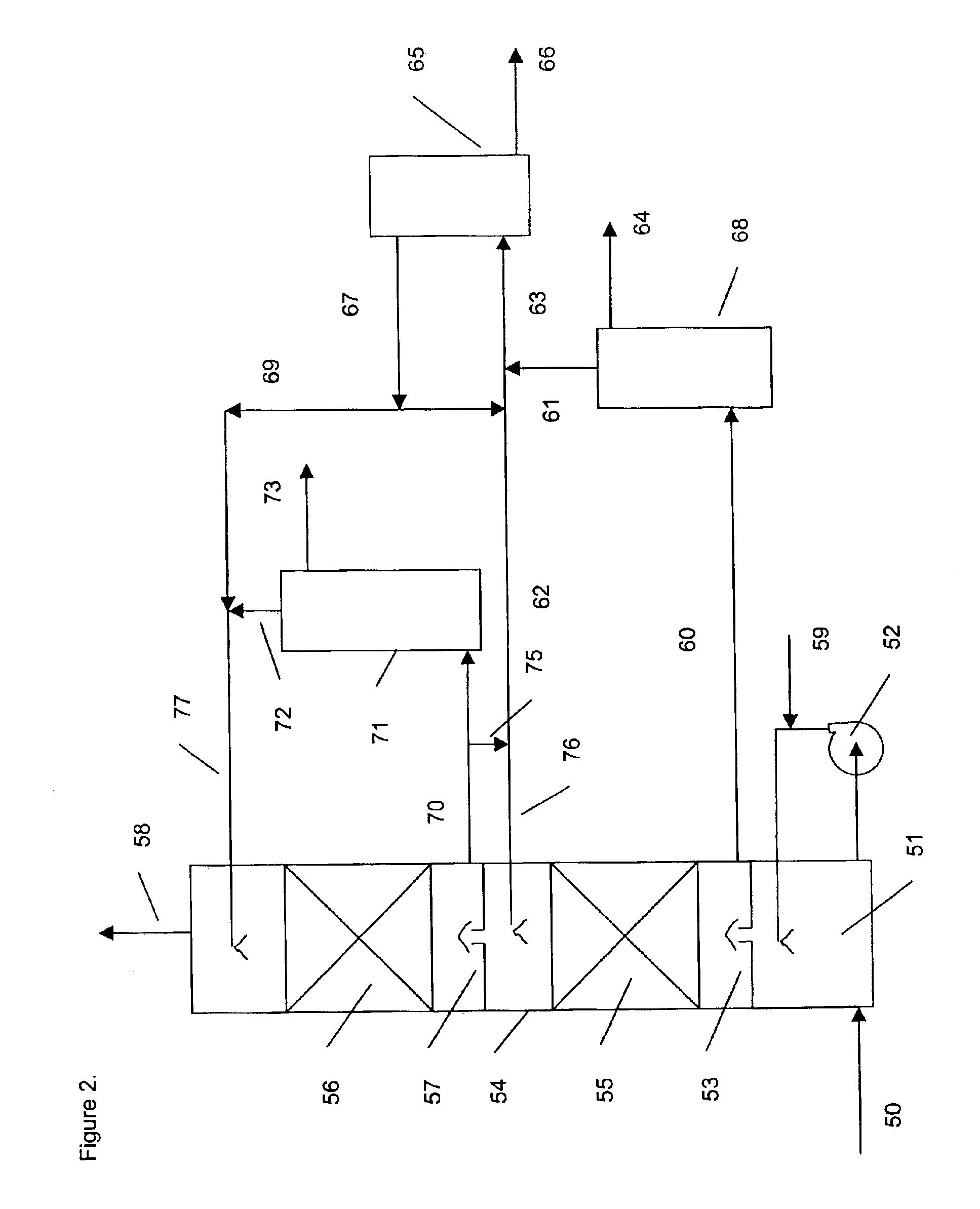
[0142]Absorbents were tested in a laboratory scale pilot apparatus, using a synthetic mixture of gases obtained by mixing mass flow controlled streams of the individual pure gases from gas cylinders. The test apparatus consisted of an 1 inch outer diameter glass absorbing tower containing a 12 inch bed of wire mesh saddles. The test absorbents were pumped to the absorbing tower by a variable speed metering pump. The absorbent at the bottom of the tower collected in a flask immersed in a thermostated bath set at 60° C. The bottom sump liquid level was controlled by means of another variable speed metering pump, which pumped the rich solvent to the top of a 5 sieve tray regeneration tower. The bottom sump of the regeneration tower was immersed in another thermostated bath, set at about 130° C., which then provided the stripping steam. An overhead condenser condensed most of the water vapor in the overhead stream of CO2 and steam and returned the water to the regeneration tower, in ord...

example 3

[0143]The apparatus of Example 2 was used to test the simultaneous removal of CO2 and nitric oxide, NO. The absorbent liquid was 3 molar in triethanolamine, 0.05 molar in FeEDTA and containing 2% sodium sulfite, with the balance being water. The feed gas flow of 1.9 liters per minute contained 9% vol. CO2 and 360 ppmv of NO, with the balance nitrogen. Analysis for NO was performed with a non-dispersive infrared gas analyzer and CO2 was determined with Gastec detector tubes. An absorbent flow rate of 15 ml / minute was used. The absorber tower bottom was thermostated to 60° C. and the regenerator bottom sump was held at about 100° C. The absorber pressure was equal to ambient. The test was run for 5 hours. The NO and CO2 removal remained essentially constant during the At the end, the outlet NO concentration was 17 ppmv for a removal of 95%. The outlet CO2 was 5%, for a removal of 44%.

[0144]

TABLE 1Tertiary Amines for CO2 CaptureMolecularCompoundWeightpKaN-methyldiethanolamine (MDEA)119...


PUM


Abstract

A process for recovering CO2 from a feed gas stream comprises treating the feed gas stream with a regenerated absorbent comprising at least one tertiary amine absorbent having a pKa for the amino function of from about 6.5 to about 9 in the presence of an oxidation inhibitor to obtain a CO2 rich stream and subsequently treating the CO2 rich stream to obtain the regenerated absorbent and a CO2 rich product stream. The feed gas stream may also include SO2 and/or NOx.

Description

FIELD OF THE INVENTION[0001]The present invention relates to a process for the capture of CO2 from gas streams which may also contain nitrogen oxides and / or sulfur oxides. The process may also provide for the simultaneous or sequential removal of other acidic contaminants and even particulate material. In one aspect, the process provides for the simultaneous or sequential removal of carbon dioxide and nitrogen oxides (NO and NO2). In another aspect, the process provides for the simultaneous or sequential removal of carbon dioxide and sulfur oxides (SO2 and SO3). In another aspect, the process provides for the removal of carbon dioxide, nitrogen oxides (NO and NO2) and sulfur oxides (SO2 and SO3). The gas stream may be a waste gas streams, such as flue gas streams, kiln gases, reverberatory furnace gases, fluidized catalytic cracker (FCC) catalyst regenerator tail gases and the like.BACKGROUND OF THE INVENTION[0002]Carbon dioxide is a useful chemical for enhanced oil recovery by mean...

Claims


Application Information

Patent Timeline
IPC IPC(8): C01B17/16B01D53/14C01B32/50
CPCB01D53/1475B01D53/1493Y02C10/06B01D53/1406Y02C20/40
Inventor HAKKA, LEO E.OUIMET, MICHEL A.
Owner CANSOLV TECH INC
Why Eureka
Try Eureka