Moister sensor

a sensor and moisture sensor technology, applied in the direction of liquid/fluent solid measurement, instruments, electrical equipment, etc., can solve the problems of permanent damage to the building surface, damage to the structure surface of the building, and damage to the mold affected areas, etc., to reduce the solubility of water, facilitate operation and/or manufacturing, and improve the effect of resistan

Inactive Publication Date: 2011-01-20
ACREO
View PDF4 Cites 93 Cited by
  • Summary
  • Abstract
  • Description
  • Claims
  • Application Information

AI Technical Summary

Benefits of technology

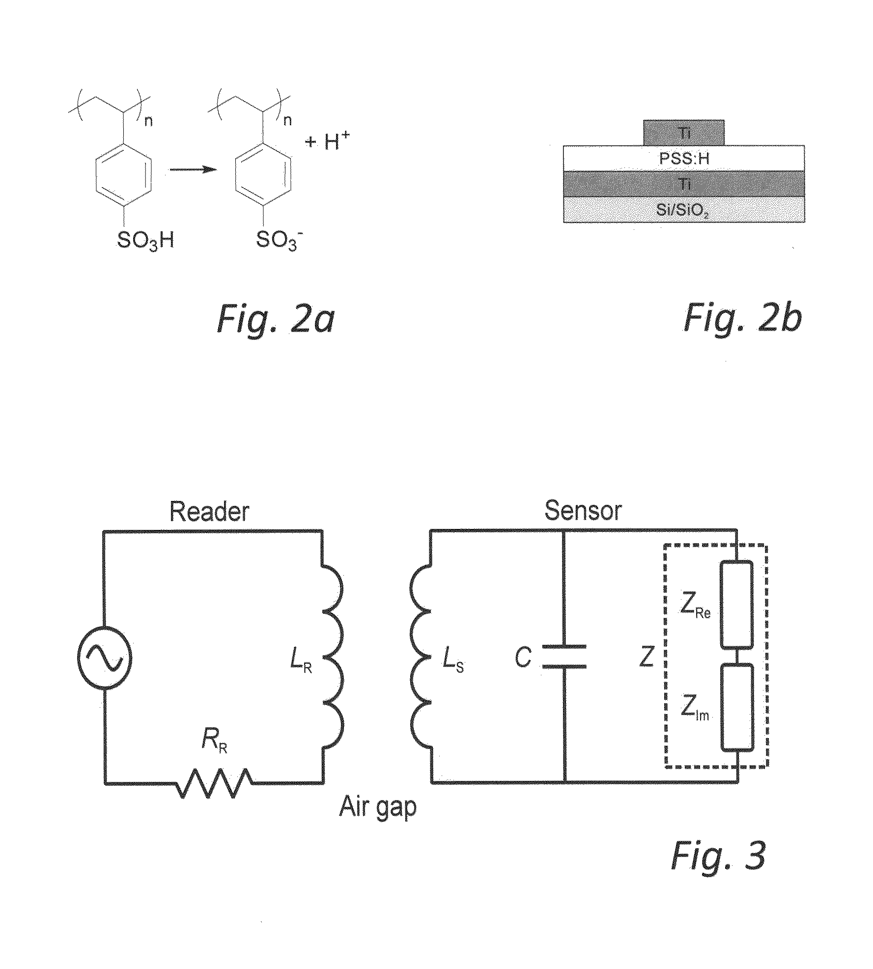
[0116]Hence, said electrolyte layer preferably comprises additives, which facilitates the operation and / or manufacturing of said sensor device or improve its resistance. For example, said oligomeric or polymeric acid of said electrolyte is preferably cross-linked, in order to reduce its solubility with water, such that e.g. water droplets which condensate on the moister reactive element do not interfere with the frequency response of the sensor, e.g. by from dissolving the electrolyte film. Further, said oligomeric or polymeric acid is preferably cross-linked by an external cross-linker. It is even more preferred that said external cross-linker has two or more glycidyl groups. Advantageously, said external cross-linker is polyethylene glycol diglycidyl ether (PEG-DEG).
[0117]When the electrolyte comprises PSS, silane derivatives, for instance the gamma-glycidoxypropyltrimethoxysilane (A 187 Silquest), may advantageously be used as a cross-linker. The cross-linker may be induced by low temperature annealing treatment (e.g. T<100° C.). The use of this type of cross-linker also facilitates the manufacturing of the moister reactive element, as the cross-linked electrolyte is less sensitive to that water drops or drops of solvent get in contact with the electrolyte during the manufacturing of the sensor.

Problems solved by technology

The presence of moister in e.g. bathroom floors, is a grave concern for many house owners as well as builders and contractors, as a neglected moister ingress may lead to mould affected areas and eventually unhealthy indoor conditions.
This method has the disadvantage of permanently damaging the building surface, requiring a craftsman to conceal the damage, and leaving visually detectable scars on the building structure surface if not mended properly.
Furthermore, known moister devices and methods are further disadvantageous in terms of operation, handling, and functionality.

Method used


Image

  • Moister sensor
  • Moister sensor
  • Moister sensor

Examples


example 2

[0172]With reference to FIG. 6, an exemplifying embodiment of a moister sensor 610 is shown. The moister sensor comprises and may be fabricated from materials that can be printed, or laminated, wherein the bottom electrode 612 may be formed by patterning an Al foil (9 μm-thick) on plastic films. The electrolyte comprises a poly(styrene sulfonic acid) sodium salt (PSSNa) (M.W 500,000) and is screen printed on the Al foil to form a 5-10 μm-thick layer. A circular top carbon electrode is afterwards screen printed on top of PSSNa, giving rise to the “dot-type” architecture for the sensor. The wireless readout output from the spectrum analyzer are displayed in FIG. 7, while the evolution of the resonant frequency versus humidity is summarized in FIG. 8. The evolution of resonant frequency versus relative humidity is clearly shown. A shift of resonant frequency from 190 kHz to 150 kHz is observed when relative humidity increases from 10% to 90%.

[0173]In FIGS. 9-12, frequency dependent ope...

example 3

[0175]FIGS. 13a and 13b illustrate further embodiments of moister active elements 1310a and 1310b formed by e.g. printing techniques, such as screen printing. The moister active elements 1310a and 1310b each comprises a first inert electrode 1311 comprising, or formed of, carbon, and a second inert electrode 1312 of an aluminum foil. A hygroscopic, humidity sensitive, electrolyte layer 1313 is arranged between the first and second electrodes 1311, 1312. For example, the electrolyte layer 1313 comprises Poly(styrene sulfonic acid) sodium salt, PSSNa (M.W 500,000). As further illustrated, a lacquer layer 1315, intended for insulating and / or protecting, may be arranged between the electrolyte 1315 and the first carbon electrode 1311.

[0176]The electrolyte layer 1313 may be formed by deposition of electrolyte paste comprising de-ionized water and isopropanol solvent onto the aluminum electrode 1312. After evaporating the solvent in the electrolyte paste, the lacquer layer 1315 is printed...

example 4

[0179]FIG. 14a schematically illustrates manufacturing steps of an integrated printed moister sensor tag 140, shown in FIG. 14b, according to an embodiment of the present invention. The moister sensor tag 140 comprises a printed electrolyte based moister active element which is integrated by screen printing into a resonant circuit also produced by screen printing.

[0180]With reference to FIG. 14a, a first step 141 comprises fabricating an antenna and bottom electrode for the sensor and additional capacitors. For example, an Al antenna is patterned on a plastic foil. A second step 142 comprises screen printing the solid electrolyte, most especially PSSNa (see Example 2). A third step 143 comprises screen printing of a protection layer, such as a laqcuer layer, onto the parts of the Al bottom pattern. The protection layer plays three key roles: defining active area for sensor head; preventing electrical short between antenna or bottom electrode and a top electrode of the sensor or an e...


PUM

PropertyMeasurementUnit
frequencyaaaaaaaaaa
frequencyaaaaaaaaaa
frequencyaaaaaaaaaa

Abstract

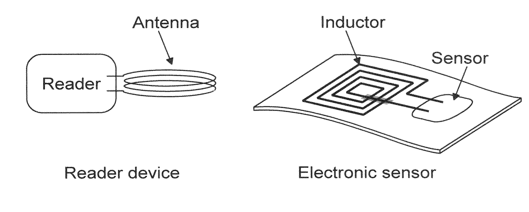
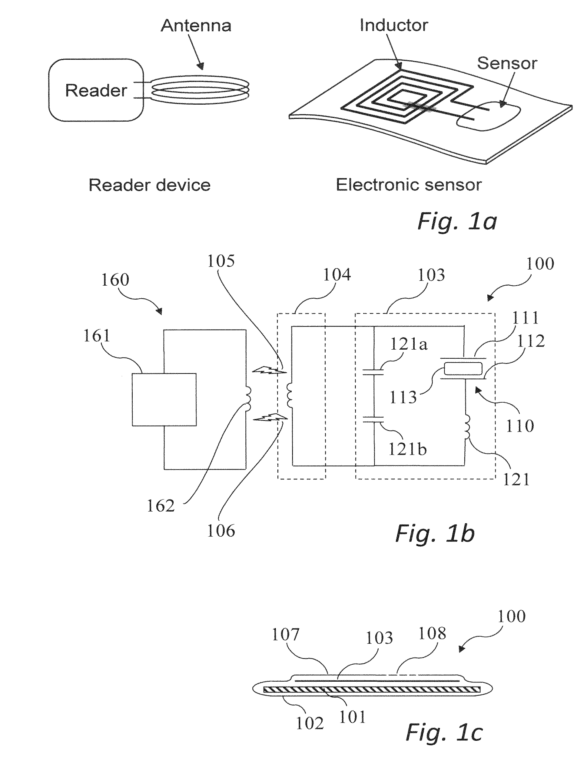
A moister sensor, for measuring moister in a building without leaving visible scars to the building surface, is provided. The moister sensor includes a flexible carrier carrying an antenna for receiving EM-radiation between 9 kHz and 11 MHz and a resonant circuit including a moister reactive element. The moister reactive element includes a hygroscopic electrolyte arranged between a first and a second electrode, wherein the electrolyte in the presence of moister forms mobile ions and provides a complex impedance at least in response to the alternating voltage, which complex impedance varies with the moister content of the electrolyte.

Description

PRIORITY STATEMENT [0001]The present application hereby claims priority under 35 U.S.C. §119 on European patent application number 09165618.1 filed Jul. 16, 2009 and hereby claims priority under 35 U.S.C. §119(e) on U.S. provisional patent application No. 61 / 213,793 filed Jul. 16, 2009, the entire contents of each of which are hereby incorporated herein by reference.TECHNICAL FIELD [0002]The invention relates to the field of moister sensors for buildings, and more specifically to moister sensors for measuring moister in building structures such as walls, floors and ceilings.BACKGROUND OF THE INVENTION[0003]The presence of moister in e.g. bathroom floors, is a grave concern for many house owners as well as builders and contractors, as a neglected moister ingress may lead to mould affected areas and eventually unhealthy indoor conditions.[0004]Today the amount of moister in a building structure, e.g. a building wall, floor or ceiling, is measured by making a hole in the surface and in...

Claims


Application Information

Patent Timeline
Patent Type & Authority Applications(United States)
IPC IPC(8): G01N27/02H05K3/00
CPCY10T29/49155G01N27/223
Inventor GUSTAFSSON, GORANCRISPIN, XAVIERBERGGREN, MAGNUSLARSSON, OSCARWANG, XIAODONG
Owner ACREO
Why Eureka
Try Eureka