Process and system for setting a patient monitor

a patient monitor and process technology, applied in the field of patient monitor setting, can solve the problems of needlessly reducing the service life of energy storage means in the case of mobile patient monitor systems, too few or unsuitable measured data available, etc., and achieves the reduction of individual measurement rates, light weight energy storage, and reduced transmission times.

Inactive Publication Date: 2007-10-04
DRAGERWERK AG
View PDF8 Cites 189 Cited by
  • Summary
  • Abstract
  • Description
  • Claims
  • Application Information

AI Technical Summary

Benefits of technology

[0011]An essential advantage of the process according to the invention is that the restriction for the patient due to the vital parameter monitoring is reduced to the adapted, necessary need. Furthermore, the amount of data to be transmitted is reduced by the process coordinated with the patient's status and the energy consumption is reduced. The patient-relevant rating criteria can be adapted due to the rated status of the patient and they may ensure a more stable alarm conditioning.
[0033]c) The additional information, which is available about the patient, makes possible the specific analysis of the data in respect to the assessment of the patient's medical risk. Thus, a mobile patient may be subject to a physical stress that leads to a brief increase in the patient's pulse. Temporary shift of the alarm limits may ensure during an observed physical activity that no needless alarm will be generated. The reliability of the evaluation of the patient's status is improved and the alarm criteria are stabilized.

Problems solved by technology

As a result, there arise situations in which too few or unsuitable measured data are available for patients who run the risk of developing a crisis or the patients are stressed needlessly, the transmission network is loaded needlessly and / or the service life of the energy storage means is needlessly reduced in case of mobile patient monitor systems.

Method used


Image

  • Process and system for setting a patient monitor
  • Process and system for setting a patient monitor

Examples


Embodiment Construction

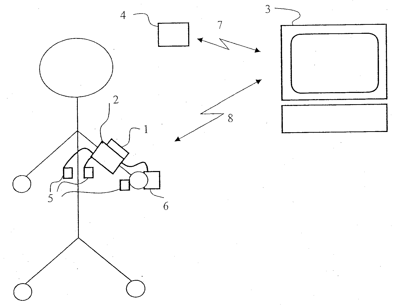
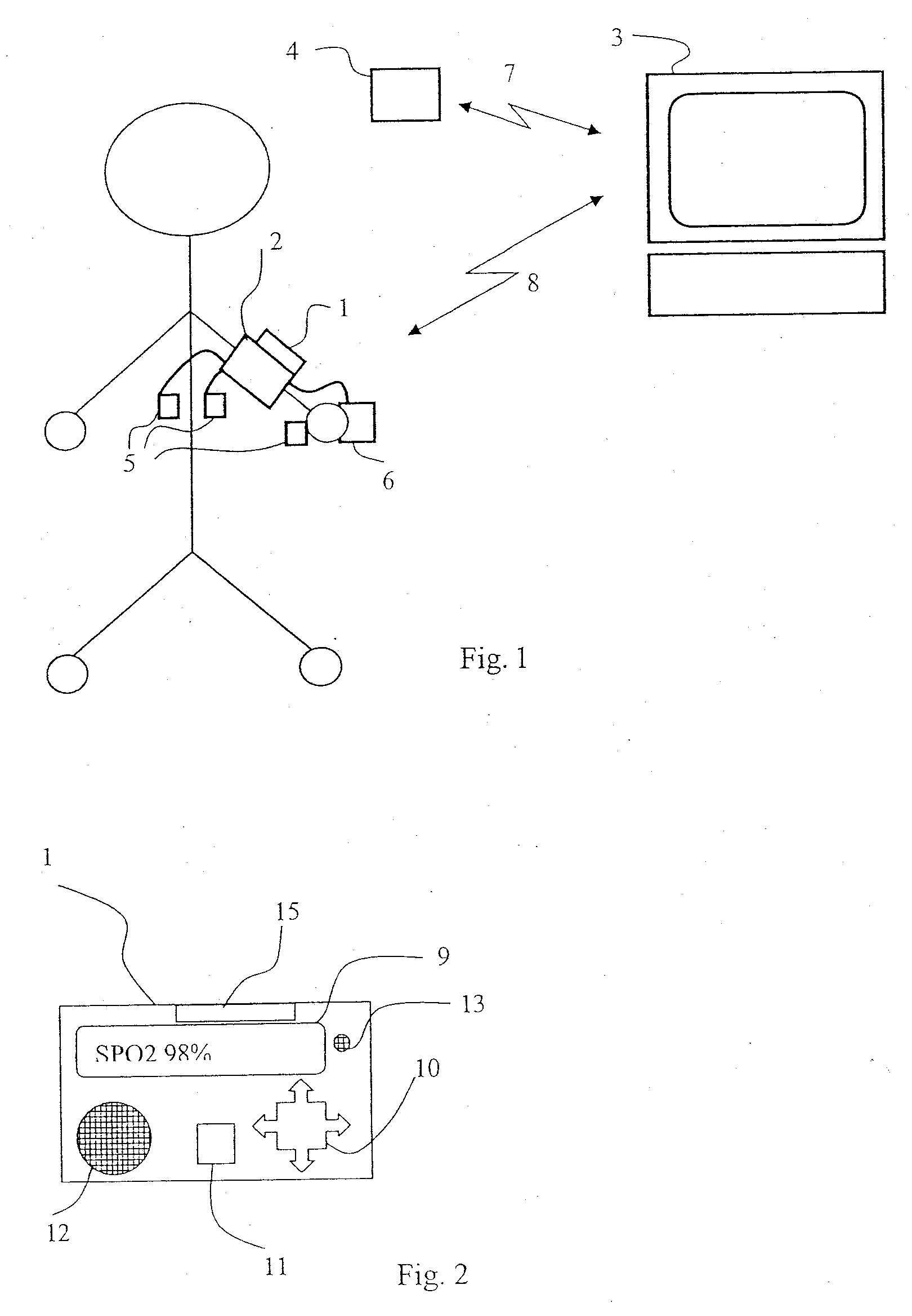
[0044]Referring to the drawings in particular, the mobile patient monitor 1 with a plurality of patient sensors for the patient being shown is in communication connection with a central station 3. The patient monitor 1 is also called a patient unit.

[0045]The patient monitor 1 is equipped for measuring the vital parameters ECG (three electrodes 5 for two leads), an oscillatory blood pressure measurement or non-invasive blood pressure (NIBP) by means of an upper arm cuff 2 and for oxygen saturation measurement SPO2 by means of a finger clip 6.

[0046]The patient monitor 1 is operated with a battery with an operating time of, e.g., 4 hours and transmits its data in a wireless manner by means of GSM-handy / mobile systems 8.

[0047]It is meaningful in this configuration for reasons of capacity to reduce the frequency of measurements as long as this is only associated with an acceptable loss of information.

[0048]The real-time ECG measurement requires a high data rate, at which it is necessary ...


PUM


Abstract

An automated process for setting a patient monitor (1) for detecting vital parameters of the patient measured by patient sensors as a function of the patient's current situation is provided. The process includes performing a statistical analysis from the measured values of the vital parameters in a computing unit for a plurality or all measured data of at least one of the measured vital parameters. The settings of the patient monitor (1) are adapted as a function of the statistical analysis performed, the adaptation of the settings pertaining at least to the vital parameters to be measured themselves, the frequency of measurements, the data quality and / or properties of the data transmission.

Description

CROSS REFERENCE TO RELATED APPLICATIONS[0001]This application claims the benefit of priority under 35 U.S.C. § 119 of DE 10 2006 015 291.3 filed Apr. 1, 2006, the entire contents of which are incorporated herein by reference.FIELD OF THE INVENTION[0002]The present invention pertains to a process for setting a patient monitor for detecting vital parameters of a patient measured by means of patient sensors as a function of the current situation of the patient.BACKGROUND OF THE INVENTION[0003]Patients are commonly provided with a monitoring system within the clinical monitoring of intensive care units. Various vital parameters are usually measured with such systems, continuously or at least very frequently. Examples of measured vital parameters are Electrocardiograms (ECGs) signals, temperature, oxygen saturation, respiration rate, heart rate, non-invasive blood pressure, and pulse transit time.[0004]A similar monitoring system is used sometimes outside the intensive care units or a sy...

Claims


Application Information

Patent Timeline
Patent Type & Authority Applications(United States)
IPC IPC(8): A61B5/00G06F19/00
CPCG06F19/3418G06F19/3406G16H40/63G16H40/67A61B5/0002
Inventor HANSMANN, HANS-ULLRICH
Owner DRAGERWERK AG
Why Eureka
Try Eureka