Flexible LED lighting strip

a technology of led lighting strips and flexible strips, which is applied in the direction of lighting and heating apparatus, printed circuit non-printed electric components association, lighting support devices, etc., can solve the problems of dangerous high-voltage operation, limited color chasing and color mixing capabilities, and existing lighting strips that do not allow the combination of flexibility and rigidity desired, and achieves greater energy efficiency

Inactive Publication Date: 2007-05-01
ALTMAN STAGE LIGHTING
View PDF5 Cites 155 Cited by
  • Summary
  • Abstract
  • Description
  • Claims
  • Application Information

AI Technical Summary

Benefits of technology

[0018]An object of the present invention is to provide a flexible LED lighting strip that can accomplish the functions of known rope lights, cove lighting, and signage lighting with greater energy efficiency and omni-directional light dispersion with color mixing, color changing, and color chasing capabilities.
[0019]It is a further object of the present invention to provide a flexible LED lighting strip that is both flexible and versatile and capable of being configured into numerous configurations and of maintaining the selected configuration.
[0020]It is yet another object of the present invention to provide a method of manufacture of a flexible LED lighting strip that is efficient and cost effective.
[0022]A minor drawback at present is the individual retail price of a single white LED. The cost decreases a bit when purchasing in larger quantities, but the overall cost is still high. At the present time of this application a single white LED from Nichia Corporation will cost $0.70 even when buying in quantities of 100,000 pieces. The cost of using LEDs can be justified in view of the energy savings, their lower current draw, the low profiles that can be achieved, and their low operating temperature. LEDs are also maintenance free and have a longer lamp life. The price of individual LEDs will fall as their luminous intensity and performance will continue to increase.
[0023]In addition, the direct generation of colored light by the selection of the type of LED used will make redundant the need for colored lenses with consequent improvements in efficiency, visibility, and cost. One particular use is in display and general lighting applications, where the long life characteristics of LEDs, their suitability for repetitive switching, their low operating temperature, and their high efficiency all contribute to qualify them for such use.

Problems solved by technology

Existing lighting strips do not allow a combination of flexibility and rigidity desired by users to configure rope lights into any selected configuration with ease.
Color chasing and color mixing capabilities are limited.
The drawbacks for neon and fluorescent lamps include difficulty in starting in cold temperatures, dangerous high-voltage operation, and the presence of mercury that in turn creates an environmental hazard.
Incandescent lamps generate a large amount of heat, have poor resistance to vibration, have short lamp life, and consume large amounts of energy with the result that most of their light energy is wasted as infrared heat energy.
This can waste up to about 90 percent of the light energy of incandescent lamps.
Previous inventions have been developed to try and accomplish this task, but have not been successful.
Although the power leads offer flexibility as far as configuring the location of the LED modules themselves, there is no overall protective housing for all the modules.
As before, this configuration will not allow for a full dispersion of light output from each light emitting diode mounted to each module.
The major disadvantage here being not all the light emitting diodes in the separate series strings can be turned on at the same time.

Method used


Image

  • Flexible LED lighting strip
  • Flexible LED lighting strip
  • Flexible LED lighting strip

Examples


Embodiment Construction

[0064]The present invention will now be described more fully with reference to the accompanying drawings where like numbers refer to like elements throughout.

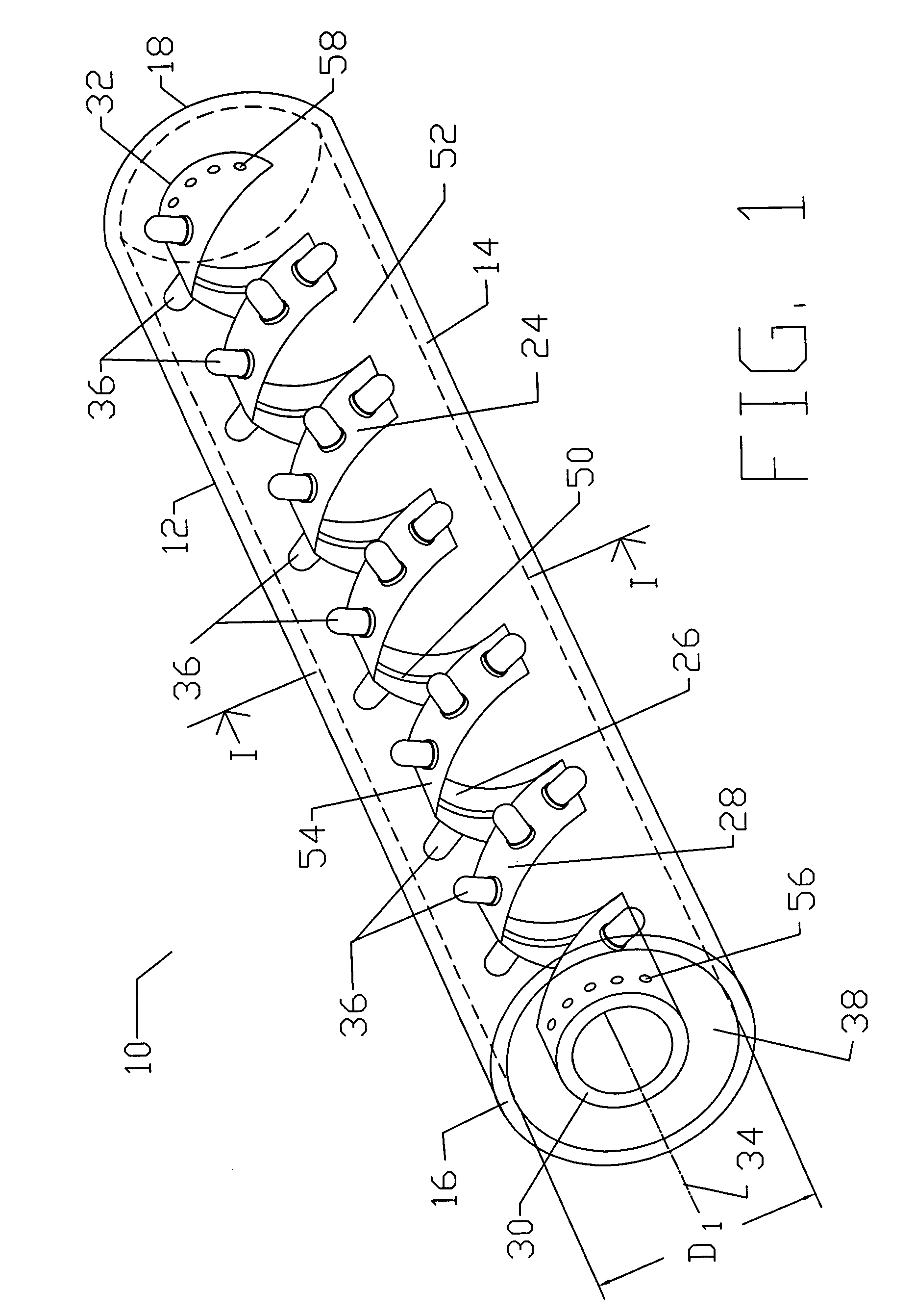
[0065]A flexible lighting strip 10 is shown in FIG. 1. Flexible lighting strip 10 is a shortened version of a lighting strip of what is generally a more extended flexible lighting strip known in the art.

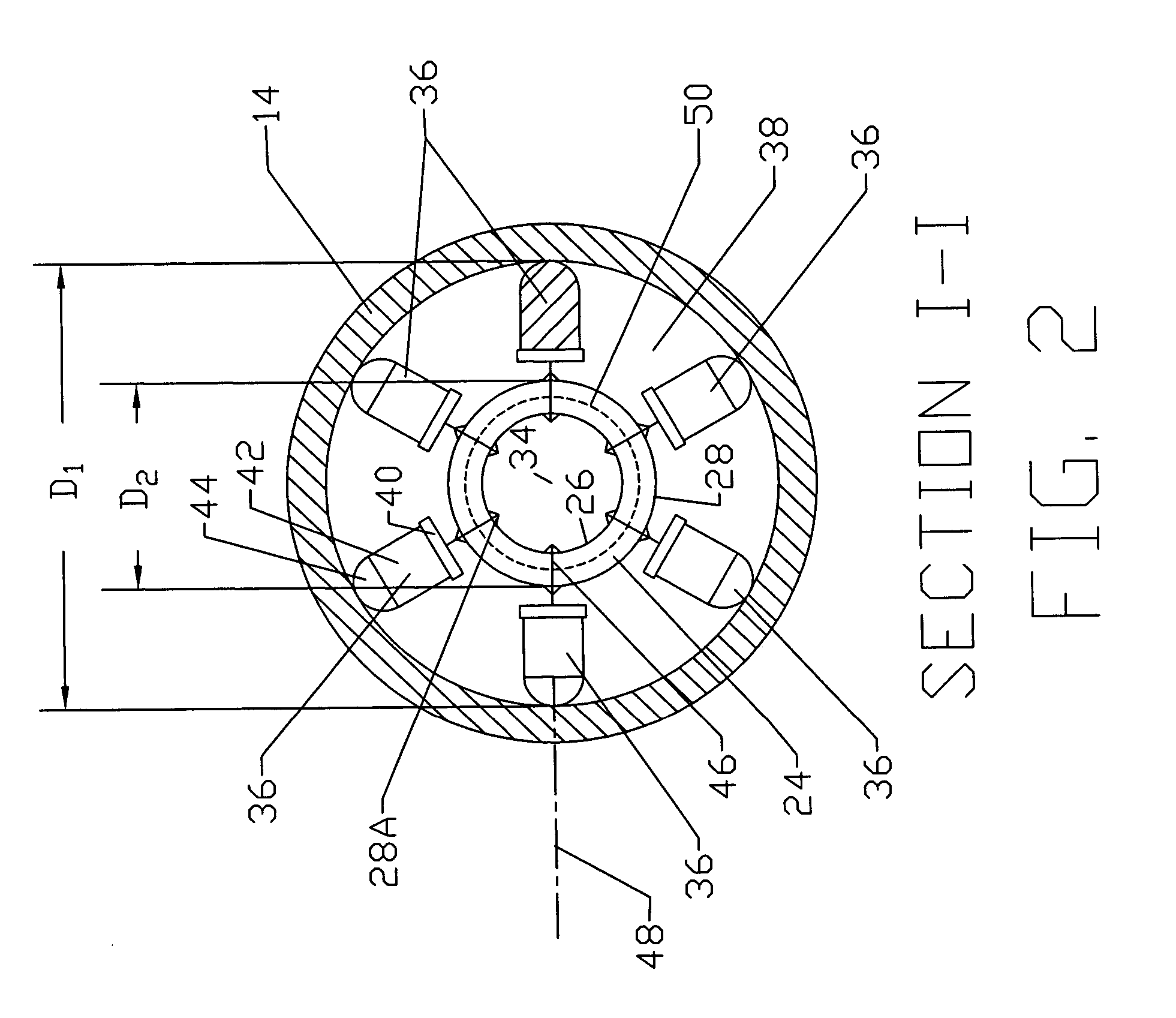
[0066]Flexible lighting strip 10 includes an elongated flexible tubular housing 12 having a smooth translucent shell, or in particular a transparent tubular shell 14 as shown, and opposed tubular ends 16 and 18 having connector end caps 20 and 22, respectively, (seen in FIG. 13) secured thereto and a flexible helical circuit board 24 configured as a open helix positioned in tubular housing 12. Flexible helical circuit board 24 is configured as a spiral helical spring having opposed continuous interior and exterior surfaces 26 and 28, respectively, and having helical circuit board opposed ends 30 and 32 positioned at tubular wall...


PUM


Abstract

A flexible lighting device includes an elongated flexible tube with a translucent tube shell and opposed tube ends and a flexible circuit board set in the tube so that it extends between the tube ends. The flexible circuit board has opposed interior and exterior surfaces. Electrical circuitry is mounted to the circuit board and connected to an external input source and an output source of electrical power. The circuit board defines a number of cut-outs, preferably those of a generally diamond shape. The device is described in two embodiments: one with inwardly directed LEDs on the circuit board directed into the tube and one with outwardly directed LEDs on the circuit board directed out of the tube. The method of making the flexible lighting device is also described.

Description

CROSS-REFERENCE TO PRIOR APPLICATION[0001]This application is a continuation-in-part (CIP) of application Ser. No. 10 / 227,710 filed on Aug. 26, 2002, now U.S. Pat. No. 6,846,094, entitled “Flexible LED Lighting Strip.”BACKGROUND OF THE INVENTION[0002]1. Field of the Invention[0003]This invention is directed to flexible lighting strips for rope lighting, cove lighting, and signage applications.[0004]2. Description of the Prior Art[0005]Flexible lighting strips, also called rope lights, are used for lighting both interior and exterior structures and can be used for sign applications. Existing lighting strips do not allow a combination of flexibility and rigidity desired by users to configure rope lights into any selected configuration with ease. Color chasing and color mixing capabilities are limited.[0006]Prior art in the sign industry includes the utilization of neon lamps, fluorescent lamps, and incandescent lamps. The drawbacks for neon and fluorescent lamps include difficulty in ...

Claims


Application Information

Patent Timeline
Patent Type & Authority Patents(United States)
IPC IPC(8): F21S13/14F21V21/32H01L25/075H05B33/00F21S4/00H05B44/00H05K1/18
CPCF21S4/007H05B33/0857H05K1/189F21Y2101/02F21Y2103/003F21Y2111/001F21Y2111/005H05K2201/051H05K2201/10106Y10S362/80F21S4/26F21Y2103/10F21Y2115/10F21Y2107/00F21Y2107/30H05B45/20
Inventor LUK, JOHN F.ALTMAN, ROBERT M.
Owner ALTMAN STAGE LIGHTING
Why Eureka
Try Eureka