AI technical title is built by Patsnap AI team. It summarizes the technical point description of the patent document.
a technology of modular pressure swing and adsorption apparatus, which is applied in the direction of chemistry apparatus and processes, separation processes, and dispersed particle separation, etc., can solve the problems of inefficient use of applied energy in conventional psa or vpsa systems, and inability to achieve large psa/vpsa prior art rotary distributor valves. achieve high energy efficiency
Inactive Publication Date: 2006-08-22
AIR PROD & CHEM INC
View PDF43 Cites 150 Cited by
Summary
Abstract
Description
Claims
Application Information
AI Technical Summary
This helps you quickly interpret patents by identifying the three key elements:
Problems solved by technology
Method used
Benefits of technology
Benefits of technology
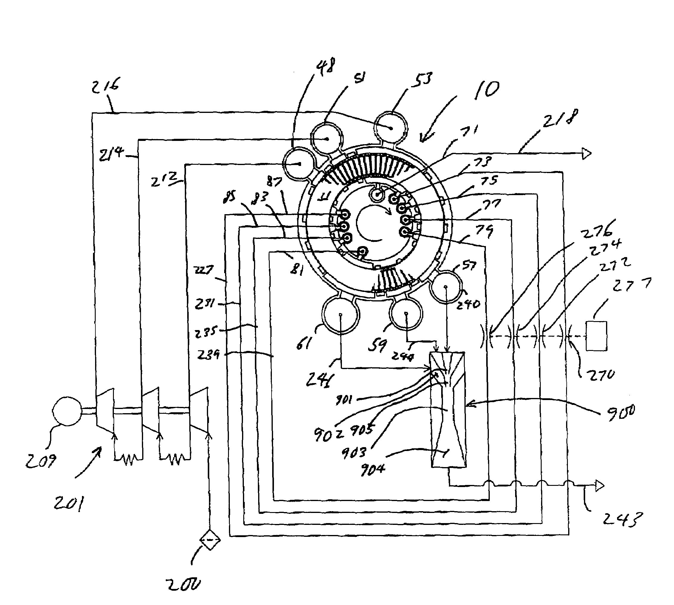
[0009]It is an object of the present invention to provide a rotary module for implementing a high frequency pressure swing adsorption process with high energy efficiency.
[0010]The rotary module, in accordance with the invention, comprises a stator and a rotor rotatably coupled to the stator. The stator includes a first stator valve surface, a second stator valve surface, a plurality of first function compartments opening into the first stator valve surface, and a plurality of second function compartments opening into the second stator valve surface. The rotor includes a first rotor valve surface in communication with the first stator valve surface, a second rotor valve surface in communication with the second stator valve surface, and a plurality of flow paths for receiving adsorbent material therein. Each said flow path includes a pair of opposite ends, and a plurality of apertures provided in the rotor valve surfaces and in communication with the flow path ends and the function ports for cyclically exposing each said flow path to a plurality of discrete pressure levels between the upper and lower pressures for maintaining uniform gas flow through the first and second function compartments.
Problems solved by technology
However, this system is often difficult and expensive to implement due to the complexity of the valving required.
Furthermore, the conventional PSA or VPSA system makes inefficient use of applied energy, because feed gas pressurization is provided by a compressor whose delivery pressure is the highest pressure of the cycle.
However, these prior art rotary distributor valves are impracticable for large PSA / VPSA units, owing to the weight of the rotating assembly.
Furthermore, since the valve faces are remote from the ends of the adsorbent beds, these rotary distributor valves have considerable dead volume for flow distribution and collection.
As a result, the prior art rotary distributor valves have poor flow distribution, particularly at high cycle frequencies.
However, with these systems, the vacuum pumps are subjected to large pressure variations, stressing the compression machinery and causing large fluctuations in overall power demand.
Because centrifugal or axial compression machinery cannot operate under such unsteady conditions, rotary lobe machines are typically used in such systems.
However, such machines have lower efficiency than modern centrifugal compressors / vacuum pumps working under steady conditions.
Method used
Image
Click on the blue label to locate the original text in one second.
Reading with bidirectional positioning of images and text.
Examples
Embodiment Construction
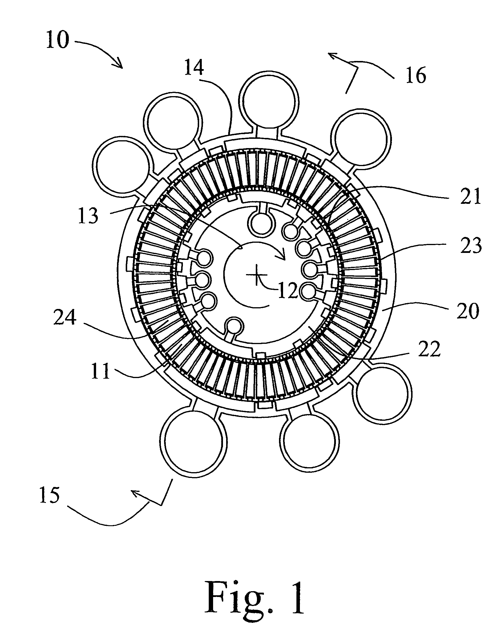
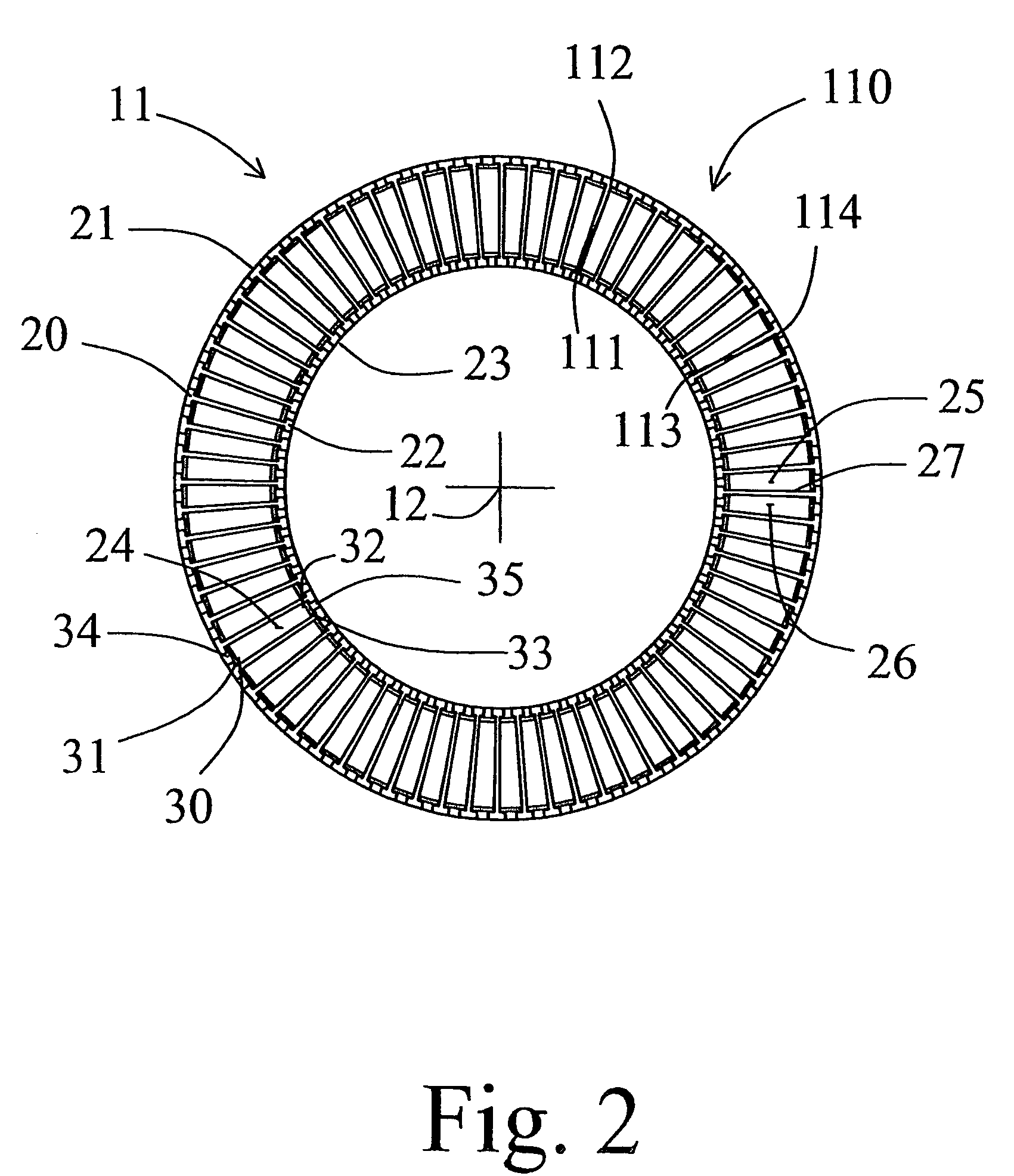
FIGS. 1, 2, 3 and 4
[0052]A rotary module 10 according to the invention is shown in FIGS. 1, 2, 3 and 4. The module includes a rotor 11 revolving about axis 12 in the direction shown by arrow 13 within stator 14. FIG. 4 is an axial section of the module 10, defined by arrows 15 and 16 in FIG. 1. FIG. 1 is a cross-section of the module 10, defined by arrows 17 and 18 in FIG. 4. FIG. 2 is the sectional view of the rotor 11 repeated from FIG. 1, with the stator deleted for clarity. FIG. 3 is the sectional view of the stator 14 repeated from FIG. 1, with details of the rotor deleted for clarity.
[0053]In general, the apparatus of the invention may be configured for flow through the adsorber elements in the radial, axial or oblique conical directions relative to the rotor axis. For operation at high cycle frequency, radial flow has the advantage that the centripetal acceleration will lie parallel to the flow path for most favourable stabilization of buoyancy-driven free convection, as well...
PUM
Property
Measurement
Unit
thickness
aaaaa
aaaaa
length
aaaaa
aaaaa
length
aaaaa
aaaaa
Abstract
A rotary module for implementing a high frequency pressure swing adsorption process comprises a stator and a rotor rotatably coupled to the stator. The stator includes a first stator valve surface, a second stator valve surface, a plurality of first function compartments opening into the first stator valve surface, and a plurality of second function compartments opening into the second stator valve surface. The rotor includes a first rotor valve surface in communication with the first stator valve surface, a second rotor valve surface in communication with the second stator valve surface, and a plurality of flow paths for receiving adsorbent material therein. Each flow path includes a pair of opposite ends, and a plurality of apertures provided in the rotor valve surfaces and in communication with the flow path ends and the function ports for cyclically exposing each flow path to a plurality of discrete pressure levels between the upper and lower pressures for maintaining uniform gas flow through the first and second function compartments.
Description
CROSS REFERENCE TO RELATED APPLICATIONS[0001]This application is a continuation-in-part of application Ser. No. 10 / 245,869, filed Sep. 16, 2002 now abandoned, which is a continuation of application Ser. No. 09 / 584,269, filed Jun. 1, 2000, now U.S. Pat. No. 6,451,095, which is a continuation of International Application No. PCT / CA98 / 01103, filed Dec. 1, 1998, which claims the benefit of U.S. Provisional Application No. 60 / 067,120, filed Dec. 1, 1997. U.S. Pat. No. 6,451,095 and application Ser. Nos. 10 / 245,869, PCT / CA98 / 01103, and 60 / 067,120 are incorporated herein by reference.FIELD OF THE INVENTION[0002]The present invention relates to an apparatus for separating gas fractions from a gas mixture having multiple gas fractions. In particular, the present invention relates to a rotary valve gas separation system having a plurality of rotating adsorbent beds disposed therein for implementing a pressure swing adsorption process for separating out the gas fractions. cl BACKGROUND OF THE ...
Claims
Application Information
Patent Timeline
Application Date:The date an application was filed.
Publication Date:The date a patent or application was officially published.
First Publication Date:The earliest publication date of a patent with the same application number.
Issue Date:Publication date of the patent grant document.
PCT Entry Date:The Entry date of PCT National Phase.
Estimated Expiry Date:The statutory expiry date of a patent right according to the Patent Law, and it is the longest term of protection that the patent right can achieve without the termination of the patent right due to other reasons(Term extension factor has been taken into account ).
Invalid Date:Actual expiry date is based on effective date or publication date of legal transaction data of invalid patent.

