Tool holder with a locking mechanism

Inactive Publication Date: 2007-09-13
LISLE CORPORATION
View PDF18 Cites 45 Cited by
  • Summary
  • Abstract
  • Description
  • Claims
  • Application Information

AI Technical Summary

Benefits of technology

[0005] Briefly, tool holder embodiments of the invention comprise a back mounting plate, a tool support plate extending generally transversly from the back mounting plate and a lock plate that is typically slidably mounted on the tool support plate and movable between a locking position and an unlocking position. The tool support plate includes one or more spaced slots extending inwardly from the front edge of the tool plate. The slidable locking plate includes arms which are movable into and out of a position over the slots to lock or release a chuck or connector element of a tool, particularly a pneumatic tool, into position in the slot. Thus, the lock plate is slidable to effect movement be

Problems solved by technology

While such tool holders are useful to mechanics in the performance of their profession, various issues associated with the storage of tools, particularly pneumatic tools remain.
Maintaining the security of such tools while not in use, for

Method used


Image

  • Tool holder with a locking mechanism
  • Tool holder with a locking mechanism
  • Tool holder with a locking mechanism

Examples


first embodiment

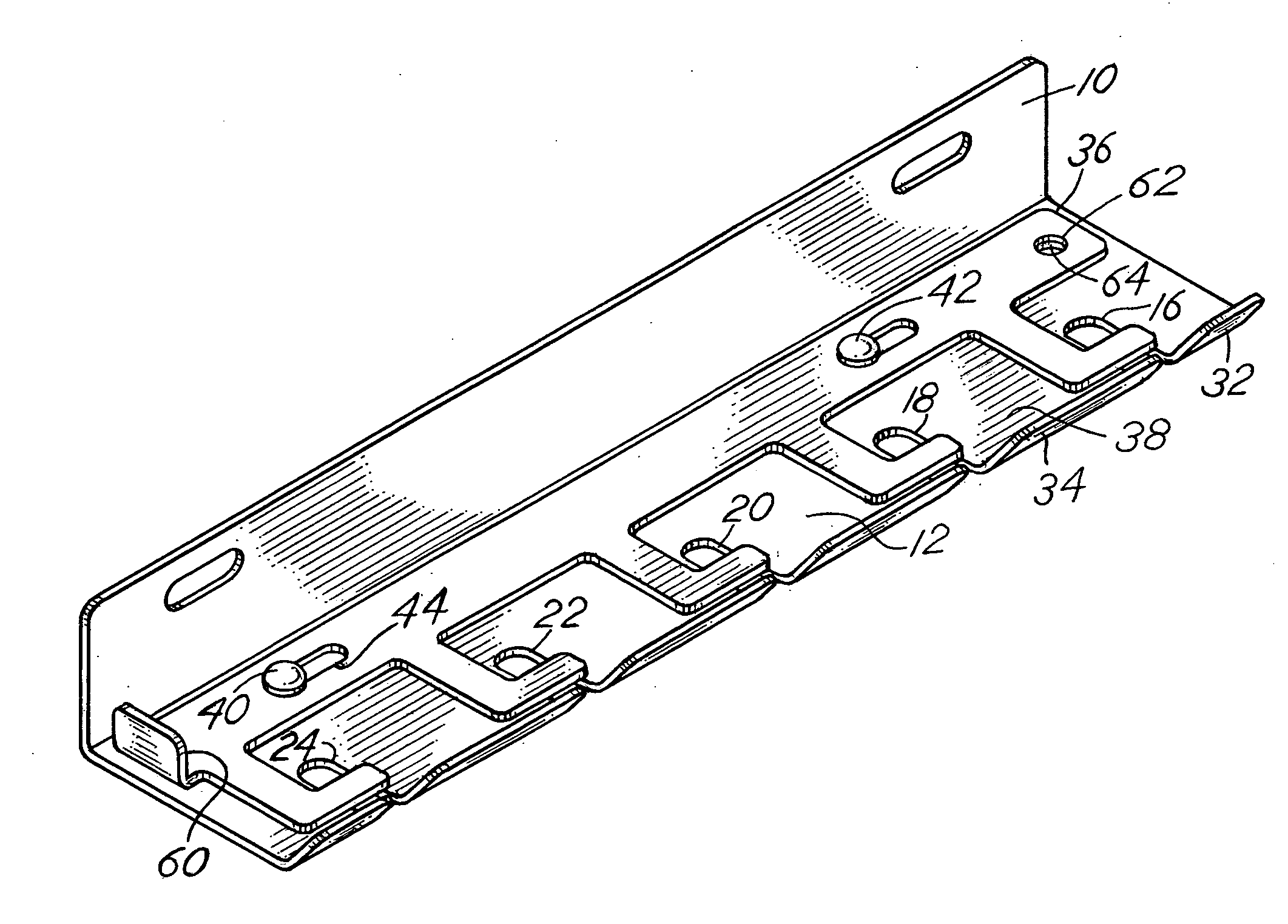
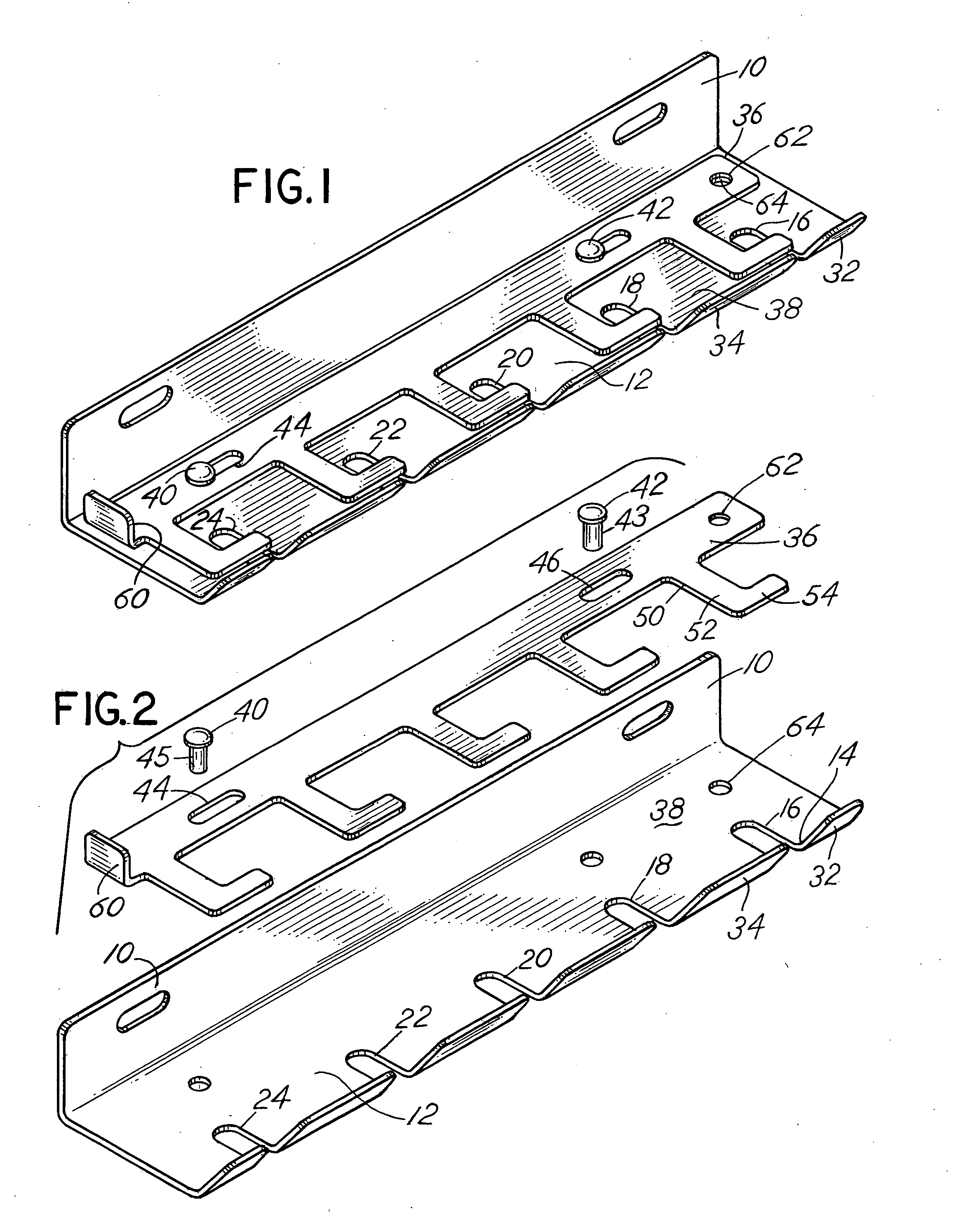
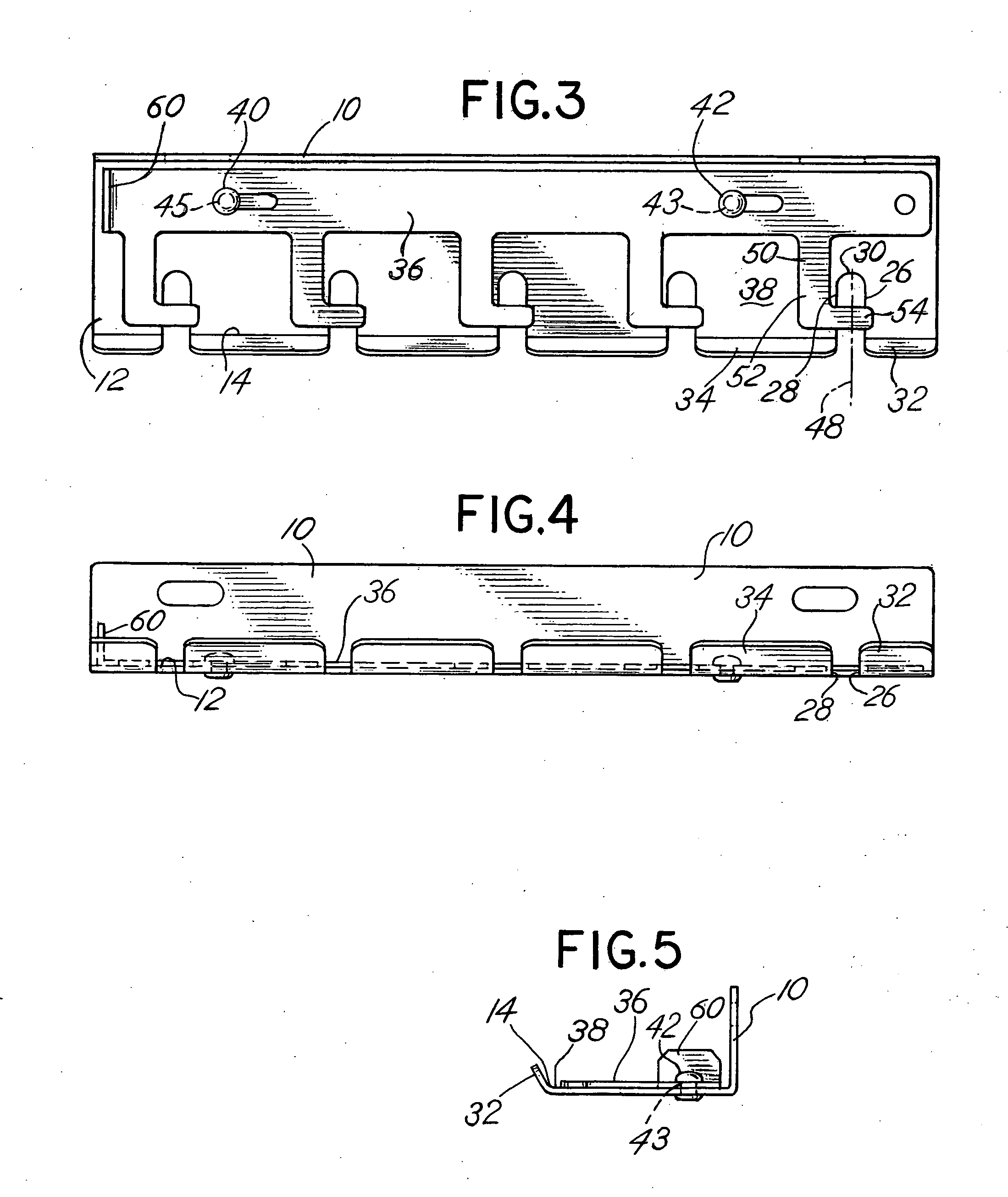
[0026] Referring to the figures, a first embodiment depicted in FIGS. 1-5A is comprised of a sheet or cast metal construction and includes a back mounting plate 10 with a generally integral, transversely extending tool support plate 12 projecting forwardly from the back mounting plate 10. The back mounting plate 10 and the forwardly extending tool support plate 12 are typically fabricated from a formed sheet steel material, although the component parts may be cast or otherwise formed, and may be formed separately and attached together by welding, for example. The tool support plate 12 includes a forward side 14 with a plurality of slots, such as slots 16, 18, 20, 22 and 24 extending from the forward side 14 toward the back mounting plate 10. The slots 16, 18, 20, 22 and 24 are generally equally sized, generally parallel and equally spaced. However, the slots may be uniquely sized in length and width and uniquely spaced one from the other. The distance of the inward extent of the slo...

second embodiment

[0031] the device comprises an elongated, L-shaped support panel 102 including a horizontal portion 103 with a vertical back plate 104 depending therefrom. The back plate 104 includes a plurality of apertures 105 that receive fasteners 41 to secure the support panel 102 to a tool cart or similar supporting structure. The back plate 104 terminates at a lower edge with a U-shaped channel 106 positioned thereon. The horizontal portion 103 terminates at an upwardly turned retaining lip 107 and includes a plurality of spaced, linear slots 108 thereon. Adjacent an end of the horizontal portion 103 is a locking aperture 109.

[0032] The device also includes a lower locking panel 110 likewise including a second horizontal portion 111 with a vertical portion 112 depending therefrom. An edge of the second horizontal portion 111 includes an upwardly extending U-shaped sleeve 113 that slidably receives the lip on the support panel 102. Likewise, a lower edge 120 of the vertical portion 112 is sli...


PUM


Abstract

A tool holder comprises a back mounting plate having a slotted tool support plate extending forwardly therefrom with a slidable lock plate mounted on the tool support plate translatable between a position wherein arms on the lock plate close the slots or open the slots which are used to hold the tools in the tool holder.

Description

BACKGROUND OF THE INVENTION [0001] In a principal aspect, the present invention relates to a tool holder and, more particularly, to a tool holder designed to be useful for holding or storing pneumatic tools. The tool holder may include a retention or locking mechanism for retaining tools placed in the holder. The invention is therefore directed to various embodiments within the scope of the claims. [0002] Automotive mechanics and repair technicians often rely upon various tools including pneumatic tools. Typically, pneumatic tools include disconnect plugs which are coupled to a pressurized air hose that supplies pressurized air to operate the tool and enable performance of various mechanical functions such as fastening, drilling, etc. Multiple types of air tools, as well as multiple types of air hose disconnect plugs are available in the marketplace. The disconnect plugs are generally designed to include a circular or peripheral slot or groove adjoined by spaced, circular ribs. Typi...

Claims


Application Information

Patent Timeline
IPC IPC(8): A47F7/00
CPCB25H3/04
Inventor WHITEHEAD, MICHAEL L.YERENA, LEOPOLDO P.FERNANDEZ CABALLERO, JESUS M.
Owner LISLE CORPORATION
Why Eureka
Try Eureka