Waveform generator for driving electromechanical device

Active Publication Date: 2014-02-25
MISONIX INC
View PDF10 Cites 260 Cited by
  • Summary
  • Abstract
  • Description
  • Claims
  • Application Information

AI Technical Summary

Benefits of technology

[0012]A further object of the present invention is to provide such an improved electrical waveform generator that can be applied to a far greater range of transducer, probe and load combinations with a minimum of hardware changes, in comparison with convention electronic signal generators.
[0013]Another obj

Problems solved by technology

One of the elements of these systems is a limiting factor to greater use of ultrasound energy in the marketplace.
In these systems, great compromises are generally made since one generator may not be designed to encompass all known variations of impedance or phase vs. frequency and power requirements that may be encountered in the field.
Standard PLL systems may require such

Method used


Image

  • Waveform generator for driving electromechanical device
  • Waveform generator for driving electromechanical device
  • Waveform generator for driving electromechanical device

Examples


Example

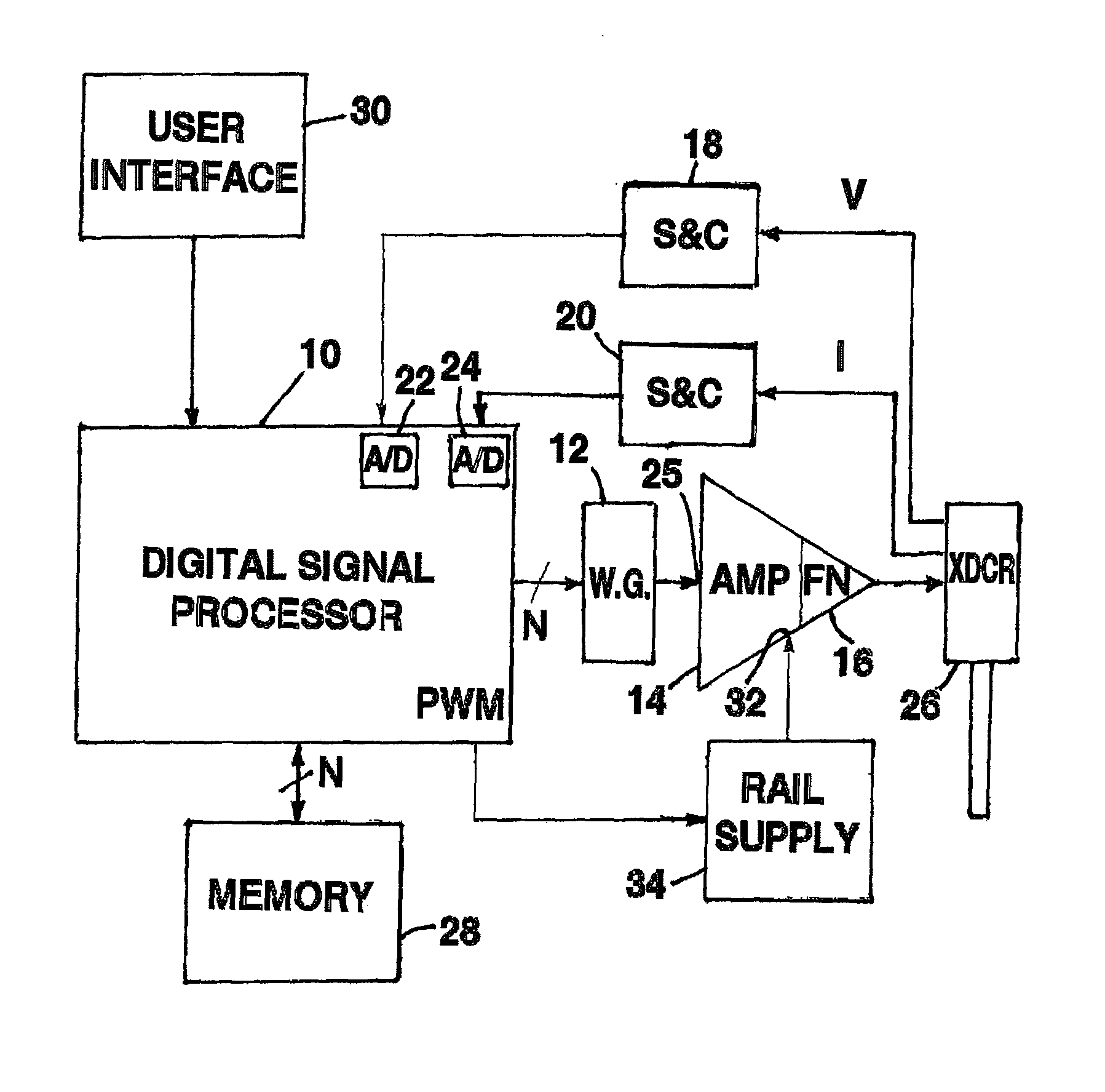
[0076]As shown in FIG. 2, an electrical waveform generator for driving an electromechanical load 26 comprises a digital signal processor 10, a waveform generator component (W.G.) 12, an amplifier section 14 with a filter network 16, sensing and conditioning (S & C) circuit components 18 and 20, and analog-to-digital converter circuitry 22 and 24. Digital processor 10 is a microcomputer, microcontroller or, preferably, a digital signal processing (DSP) controller chip. Waveform generator component 12 is a operationally connected to the output data bus of the DSP 10 for generating voltage output signals having a frequency that is a function of the data output of DSP 10.

[0077]Amplifier section 14 may be of an analog type or, preferably, a switching amp type. Amplifier section 14 is connected at a control input 25 to an output of waveform generator component 12 for variably increasing the frequency of the waveform in response to a signal on the control input. A rail supply 34 or other c...


PUM


Abstract

An electrical waveform generator for driving an electromechanical load includes a digital signal processor connected to a waveform generator component in turn connected to an amplifier section with a filter network, the latter being connected to sensing and conditioning circuit componentry that is in turn connected to analog-to-digital converter circuitry. A digital memory stores digitized voltage and current waveform information. The processor determines a phase difference between voltage and current waveforms, compares the determined phase difference to a phase difference command and generates a phase error or correction signal. The processor also generates an amplitude error signal for inducing the amplifier section to change its output amplitude to result in a predetermined amplitude error level for a respective one of the voltage and current waveforms.

Description

CROSS-REFERENCE TO RELATED APPLICATIONS[0001]This application is a continuation of application Ser. No. 13 / 065,644 filed Mar. 25, 2011, which in turn is a continuation of application Ser. No. 12 / 462,335 filed 31 Jul. 2009, which is a continuation-in-part of application Ser. No. 12 / 157,707 filed Jun. 12, 2008, which claims the benefit of U.S. Provisional Patent Application No. 60 / 934,546 filed 14 Jun. 2007 and U.S. Provisional Patent Application No. 61 / 070,091 filed 20 Mar. 2008. Parent application Ser. No. 12 / 462,335 is also a continuation-in-part of application Ser. No. 12 / 290,733 filed Nov. 3, 2008.BACKGROUND OF THE INVENTION[0002]This invention relates to an electrical waveform generator for driving electromechanical devices such as piezoelectric and magnetostrictive transducers.[0003]Tools that are made to vibrate at frequencies above the range of human hearing have been used in science, medicine and industry for many decades. Applications such as cell disruption, bloodless surg...

Claims


Application Information

Patent Timeline
IPC IPC(8): H01L41/09H01L41/00
CPCB06B2201/58B06B2201/55H01L41/042B06B1/0261B06B1/0246B06B2201/76B06B2201/72H01L41/09H01L41/00H10N30/802
Inventor ROSE, EMERYMANNA, RONALD R.PANTANO, SALVATORE
Owner MISONIX INC
Why Eureka
Try Eureka