Label applicator with RFID antenna

Inactive Publication Date: 2005-09-08
INTERMEC IP
View PDF6 Cites 13 Cited by
  • Summary
  • Abstract
  • Description
  • Claims
  • Application Information

AI Technical Summary

Benefits of technology

[0010] Radio frequency transponders (also known as “RFID tags”) generally include an antenna and integrated memory circuit with read/write capability used to store digital information, such as an electrically erasable programmable read only memory (EEPROM) or similar electronic device. Active RFID tags include their own radio transceiver a

Problems solved by technology

As a result they are small and inexpensive with limited range, resolution, and data storage capacity.
If the RFID tag is written to before it reaches the applicator head, there

Method used


Image

  • Label applicator with RFID antenna
  • Label applicator with RFID antenna

Examples


Example

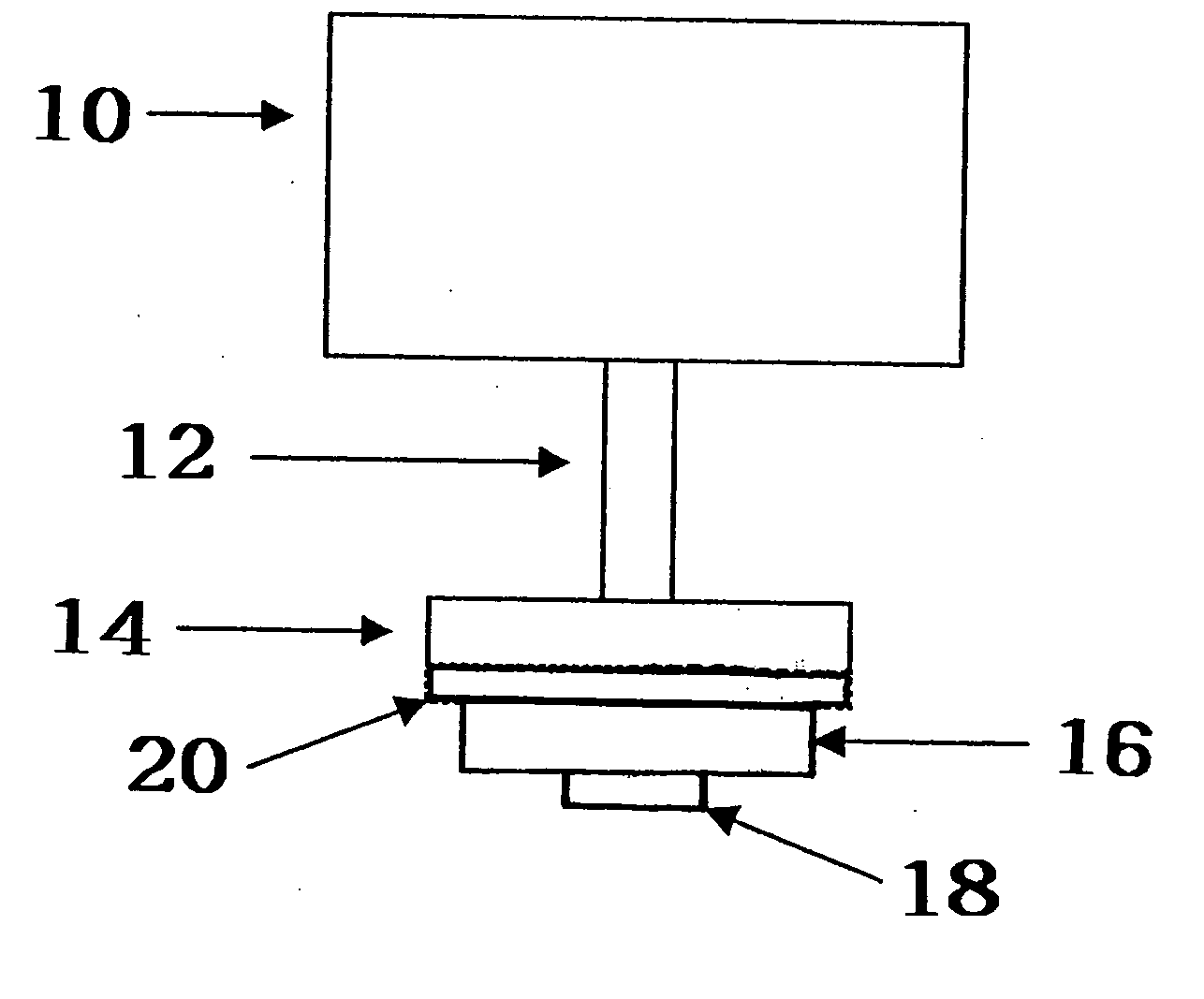
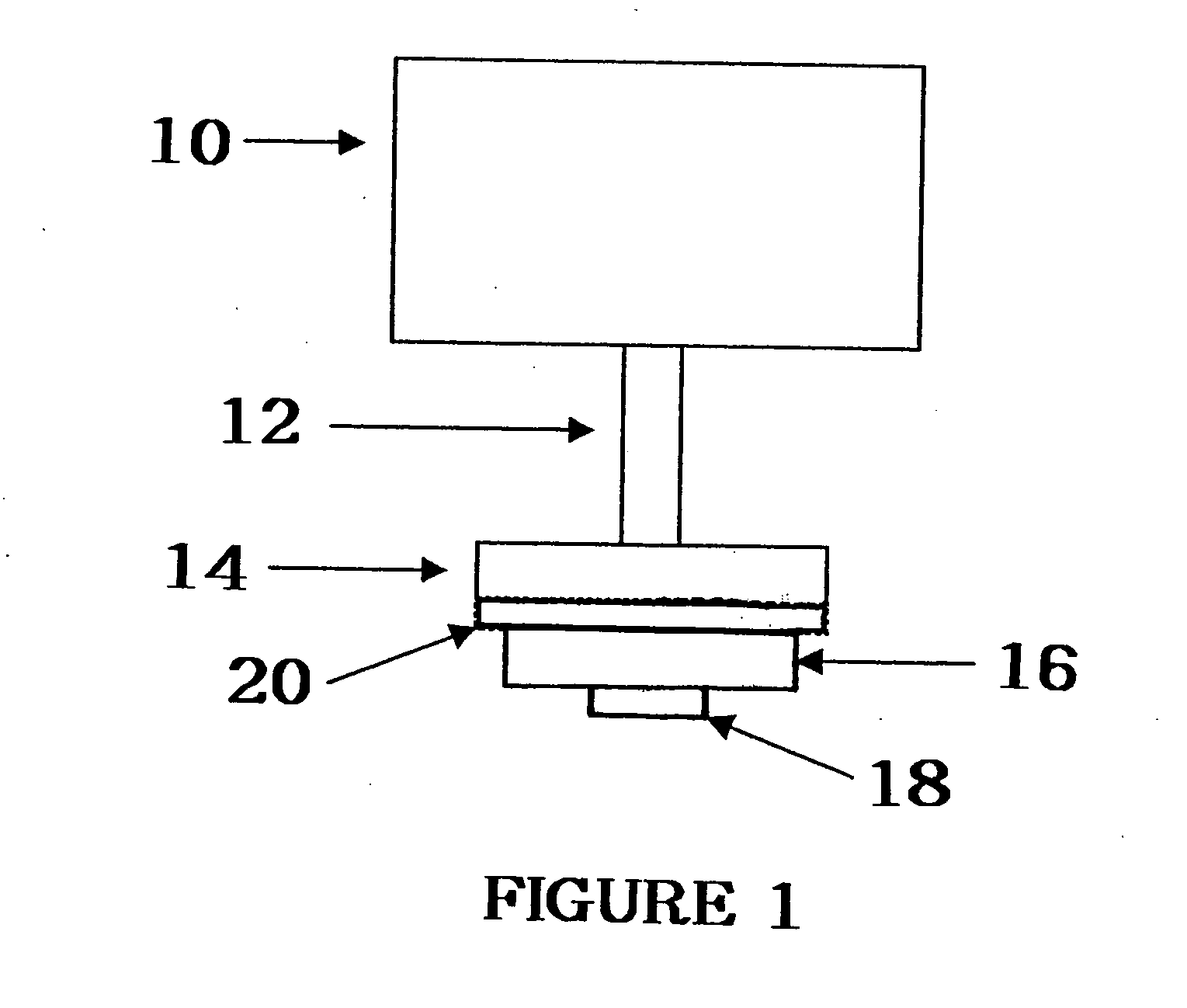
[0017] Radio frequency transponders (also known as “RFID tags”) generally include an antenna and integrated memory circuit with read / write capability used to store digital information, such as an electrically erasable programmable read only memory (EEPROM) or similar electronic device. Active RFID tags include their own radio transceiver and power source (battery) and are generally sealed within a molded plastic housing or “button”. Passive RFID tags are energized to transmit and receive data by an electromagnetic field and do not include a radio transceiver or power source. As a result they are small and inexpensive with limited range, resolution, and data storage capacity.

[0018] Passive RFID tag “inserts” used in the Automatic Identification Industry are typically laminated or inserted into a paper or plastic label stock backed with pressure sensitive adhesive for applying the printed label to a carton, pallet, airline baggage, parcel, or the other article to be tracked. These la...


PUM


Abstract

A label applicator with a patch antenna or in the label applicator. The antenna is able to read and/or write to an RFID tag embedded in the label as the label is being applied to an object. The antenna can write the most current information to the RFID tag as the label is being applied. The antenna also can read the RFID tag and identify failed or damaged tags so they can be disguarded.

Description

[0001] This application claims the benefit of U.S. provisional application 60 / 504,780 entitled Label Applicator with RFID Antenna copy filed Sep. 18, 2003.BACKGROUND OF THE INVENTION [0002] 1. Field of the Invention [0003] The present invention relates to smart labels. More specifically it relates to a label applicator with an integrated RFID antenna for reading and / or writing to a smart label containing an RFID transponder. [0004] 2. Description of Related Art [0005] RFID labels provide a good reliable labeling solution where a line of site to a bar code label is unavailable. RFID smart labels also provide fast, reliable, accurate data collection without human error or replication. [0006] No smart label applicator exists today in the Automatic Identification Industry that is designed to read / write to smart labels during label application. [0007] There is a need for a labeling system that can read / write to smart labels as they are applied to an article. [0008] There is a need for a ...

Claims


Application Information

Patent Timeline
IPC IPC(8): G06K7/00
CPCB65C9/36G06K2017/0083B65C2009/405B65C2009/0003
Inventor ADAMS, MATTHEW THOMASCONWELL, KEVIN
Owner INTERMEC IP
Why Eureka
Try Eureka