Semiconductor ring laser gyroscope

a laser gyroscope and semiconductor technology, applied in the direction of speed measurement using gyroscopic effects, instruments, surveying and navigation, etc., can solve the problems of difficult or even impossible to detect an angular velocity, high cost of semiconductor optical amplifiers, and high cost of polarization preserving fibers and couplers using such polarization preserving fibers, etc., to achieve excellent sensitivity and small and inexpensive

Active Publication Date: 2010-02-25
MINEBEAMITSUMI INC
View PDF1 Cites 14 Cited by
  • Summary
  • Abstract
  • Description
  • Claims
  • Application Information

AI Technical Summary

Benefits of technology

[0014]The present invention has been made in light of the problems described above, and it is a primary object of the present invention to provide a semiconductor ring laser gyroscope which is small and inexpensive and at the same time is capable of detecting an angular velocity with excellent sensitivity.

Problems solved by technology

However, the present inventors, while designing to reduce the size of an optical fiber loop for the purpose of downsizing the semiconductor ring laser gyroscope, found out that it is difficult or even impossible to detect an angular velocity when the optical fiber loop has a diameter of, for example, about 100 mm (almost a palm size).
The semiconductor optical amplifier, however, is expensive, and so it is proposed, in order to provide a low-cost semiconductor ring laser gyroscope, to use as a light source a semiconductor laser (Fabry-Perot semiconductor) as employed, for example, in an optical pickup of an optical disk drive, which emits a laser beam having a large spectral line width but is inexpensive.
However, a polarization preserving fiber and a coupler using such a polarization preserving fiber are expensive.
Moreover, it is difficult to detect rotation direction in the semiconductor ring laser gyroscope using an optical fiber.

Method used


Image

  • Semiconductor ring laser gyroscope
  • Semiconductor ring laser gyroscope
  • Semiconductor ring laser gyroscope

Examples


Embodiment Construction

[0028]Exemplary embodiments of the present invention will hereinafter be described with reference to the accompanying drawings.

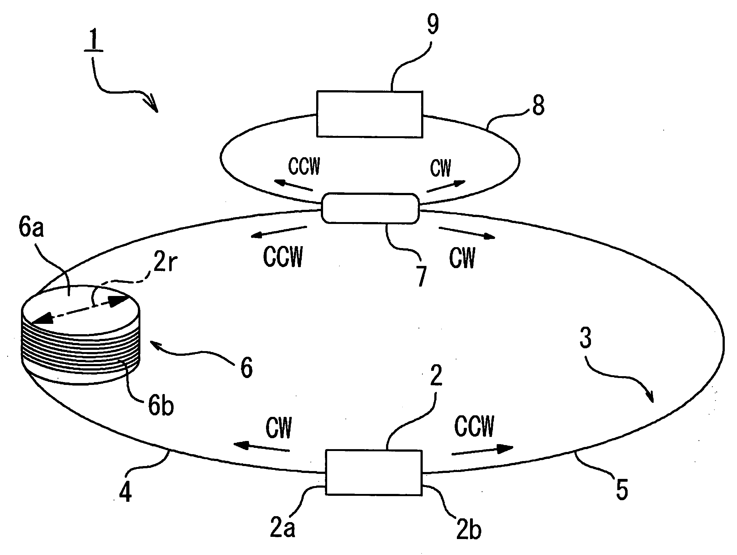
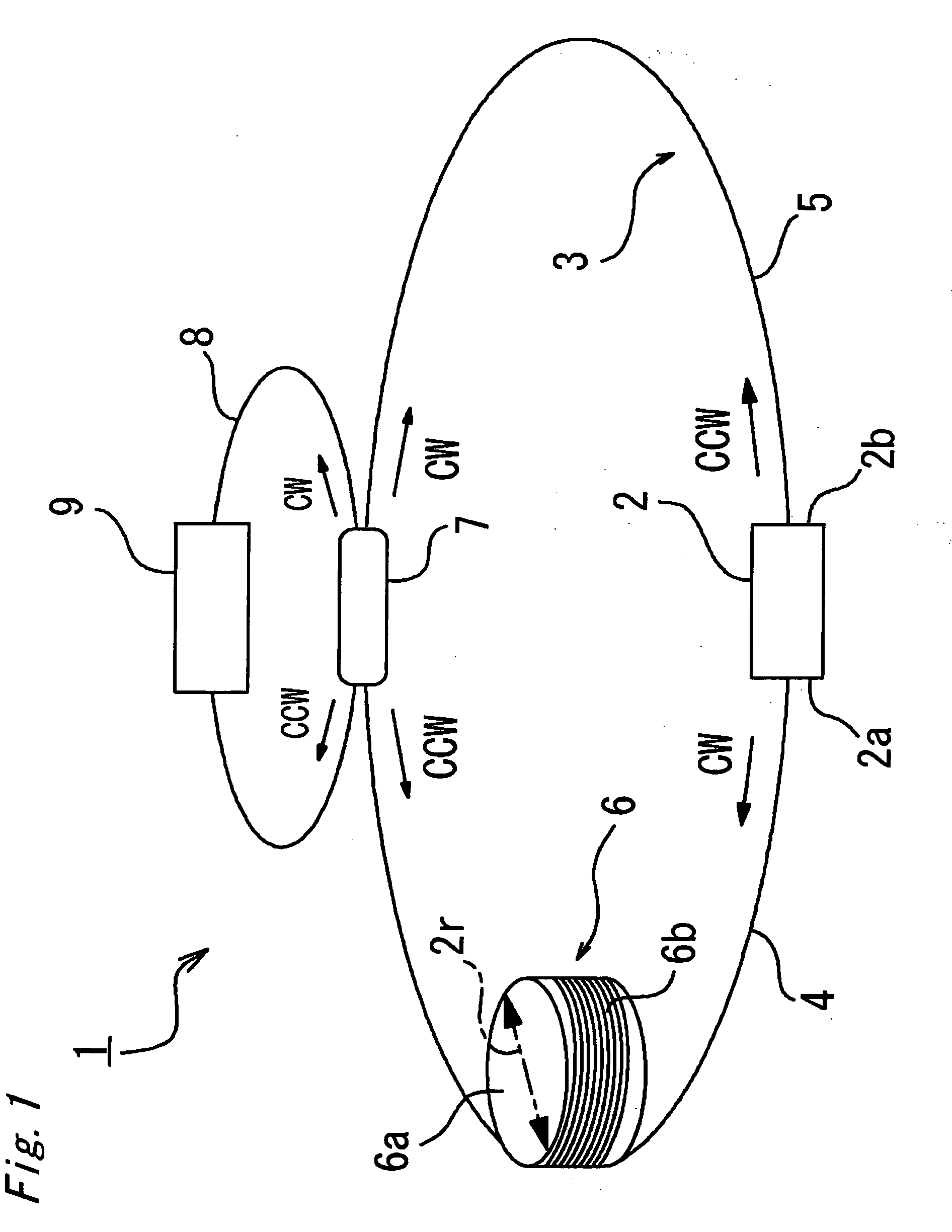
[0029]FIG. 1 schematically shows a semiconductor ring laser gyroscope 1 according to a first embodiment of the present invention. Referring to FIG. 1, the semiconductor ring laser gyroscope 1 according to the first embodiment includes a semiconductor laser 2 to emit a clockwise laser beam CW (hereinafter referred to as CW light) and a counter-clockwise laser beam CCW (hereinafter referred to as CCW light) respectively from its both end surfaces 2a and 2b, an optical fiber ring 3 through which the CW light and the CCW light emitted from the end surfaces 2a and 2b of the semiconductor laser 2 propagate in the respective opposite directions, an optical splitter 7 to extract and separate parts of the CW and CCW lights, and an optical detection unit 9 to detect an angular velocity based on a frequency (beat frequency) of a beat signal generated by the CW and CCW ...


PUM


Abstract

A semiconductor ring laser gyroscope includes: a semiconductor laser for emitting two lights from both end surfaces thereof; an optical fiber ring through which the two light propagate in the respective opposite directions, which, in association with the semiconductor laser, constitutes a laser resonator, and which includes a sensor coil made of an optical fiber wound in a multilayer manner; and an optical detection unit for detecting a rotational angular velocity based on beat frequencies of the two lights, wherein an expression: 2ΔFbeat<sub2>—</sub2>max<Frlg≦10ΔFbeat<sub2>—</sub2>min is satisfied in which Frlg=C/nL, where ΔFbeat<sub2>—</sub2>max and ΔFbeat<sub2>—</sub2>min are beat frequencies corresponding respectively to the upper and lower limits of an angular velocity measuring range, Frlg is a ring resonance frequency, C is a light speed, n is a refractive index of the optical fiber, and L is an overall length of the optical fiber.

Description

BACKGROUND OF THE INVENTION[0001]1. Field of the Invention[0002]The present invention relates to a semiconductor ring laser gyroscope in which a rotational angular velocity of an object is detected on the basis of a beat signal which is generated due to the Sagnac effect when lights emitted from the both end surfaces of a semiconductor laser circulate through an optical fiber loop in respective opposite directions, and relates particularly to a semiconductor ring laser gyroscope suitable for downsizing.[0003]2. Description of the Related Art[0004]An optical fiber gyroscope which utilizes the Sagnac effect to measure a rotational angular velocity (angular velocity) of an object is widely used mainly in the aircraft and rocket industries. In a conventional optical fiber gyroscope, a light emitted from an end surface of a light source is separated by a photocoupler and introduced into an optical fiber loop so as to propagate in respective opposite directions, and an angular velocity is...

Claims


Application Information

Patent Timeline
Patent Type & Authority Applications(United States)
IPC IPC(8): G01C19/72
CPCG01C19/66
Inventor KITAMURA, ATSUSHISUGAWARA, MIKI
Owner MINEBEAMITSUMI INC
Why Eureka
Try Eureka