End mill

a technology of end mills and end mills, which is applied in the direction of metal-working equipment, workpieces, milling equipment, etc., can solve the problems of beck end mills with several deficiencies and limitations, catastrophic tool failure, and rejected work pieces

Inactive Publication Date: 2006-03-30
CALAMIA GUY ALLEN
View PDF11 Cites 74 Cited by
  • Summary
  • Abstract
  • Description
  • Claims
  • Application Information

AI Technical Summary

Benefits of technology

[0008] The present invention provides for three tooth face walls and a variable depth tooth face wherein the depth of the tooth face is greatest at the terminal end of the cutting section of the end mill and less at the upper end of the helical cutting section. This allows the end mill to take a more aggressive or deeper cut when the end mill first touches the cutting surface. As the end mill cuts down into the work material, the gradual reduction in tooth face depth provides for a shallower cut with less force directed toward the upper portion of the cutting teeth where catastrophic failure frequently occurs. This variable tooth depth, especially in combination with the variable margin described herein, greatly reduces tool deflection and catastrophic failure, allows for higher feed rates and reduces the harmonic distortion created by existing end mill cutters.
[0009] Further, end mills in the prior art are manufactured with a dish which begins at the tip of the terminal cutting edge of each cutting tooth with a straight concave angle from the tip of the cutting edge face toward the axis of the end mill. Running at high speeds, this design results in tool deflection, squalls, chatter and vibration, particularly in the work piece's bottom finish in deep axial cuts and thin wall applications. The present invention includes a stabilizing flat land at the outer most region of the end cutting edge of the end mill. Depending on the diameter size of the end mill, this flat region is between 89° and 90° from the axis of the mill and extends inward from the tip of the end cutting face between 4 to 10 percent of the cutter diameter and then transitions into a concave angle toward the axial section of the tooth, thereby reducing and, at times, eliminating squalls, chatter and vibration, as well as a marked improvement in the work piece's bottom finish. Preferred embodiments of the invention include a straight and a curved dish.
[0012] The present invention includes a groove type chip breaker wherein the peripheral corners of the groove are rounded not sharp. By including rounded peripheral corners at this area of the groove, the end mill achieved more than a 30 percent improvement in load versus existing groove designs. The smaller chips produced by this design also results in reduced volume of chips and a freer cutting end mill that is able to remain stable at high machine rates.
[0013] Further, in a preferred embodiment, the present invention utilizes ultra-fine micro grain tungsten carbide materials with a cobalt content which varies throughout the length of the end mill. This allows for added strength and reduced costs while at the same time allowing for the high speed applications needed in today's marketplace.

Problems solved by technology

However, while an improvement over prior end mills, the Beck end mill has several deficiencies and limitations.
First, modern end mills running at high rpm's create tool deflection leading to catastrophic tool failure, unsatisfactory finishes and rejected work pieces.
Second, the design of modern end mills creates a downward pressure on the end mill, forcing it to come out of its holder, again leading to tool deflection and catastrophic failure.
Third, end mills with chipbreakers on their cutting edges consume more load power than non-chip breaker end mills and lead to chip packing in the flute.
The chip size produced by such end mills is not conducive to clean machining because the over-sized chips tend to clog the work piece.
More importantly, the large chip size created by these end mills hinders overnight, non-operator, operations because they tend to fill the chip receptacle bucket too quickly, thereby requiring the services of an operator to service the machine after hours.
First, the margin of an end mill is the unrelieved portion of the periphery of the land adjacent to the cutting edge.
Running at high speeds, this design results in tool deflection, squalls, chatter and vibration, particularly in the work piece's bottom finish in deep axial cuts and thin wall applications.
Long steel chips are dangerous to the operator, and cumbersome to handle, and they may clog or twist around the tool causing damage or increased maintenance.
These chipbreakers consume more power load than non-chip break end mills, create conditions limiting high speed machining and cause chip packing in the flute.
The chip size created by these chipbreakers, moreover, hinders overnight, non-operator, operations because they tend to fill chip receptacles too quickly, thereby requiring the services of an operator to service the machine after hours.

Method used


Image

  • End mill
  • End mill
  • End mill

Examples


Embodiment Construction

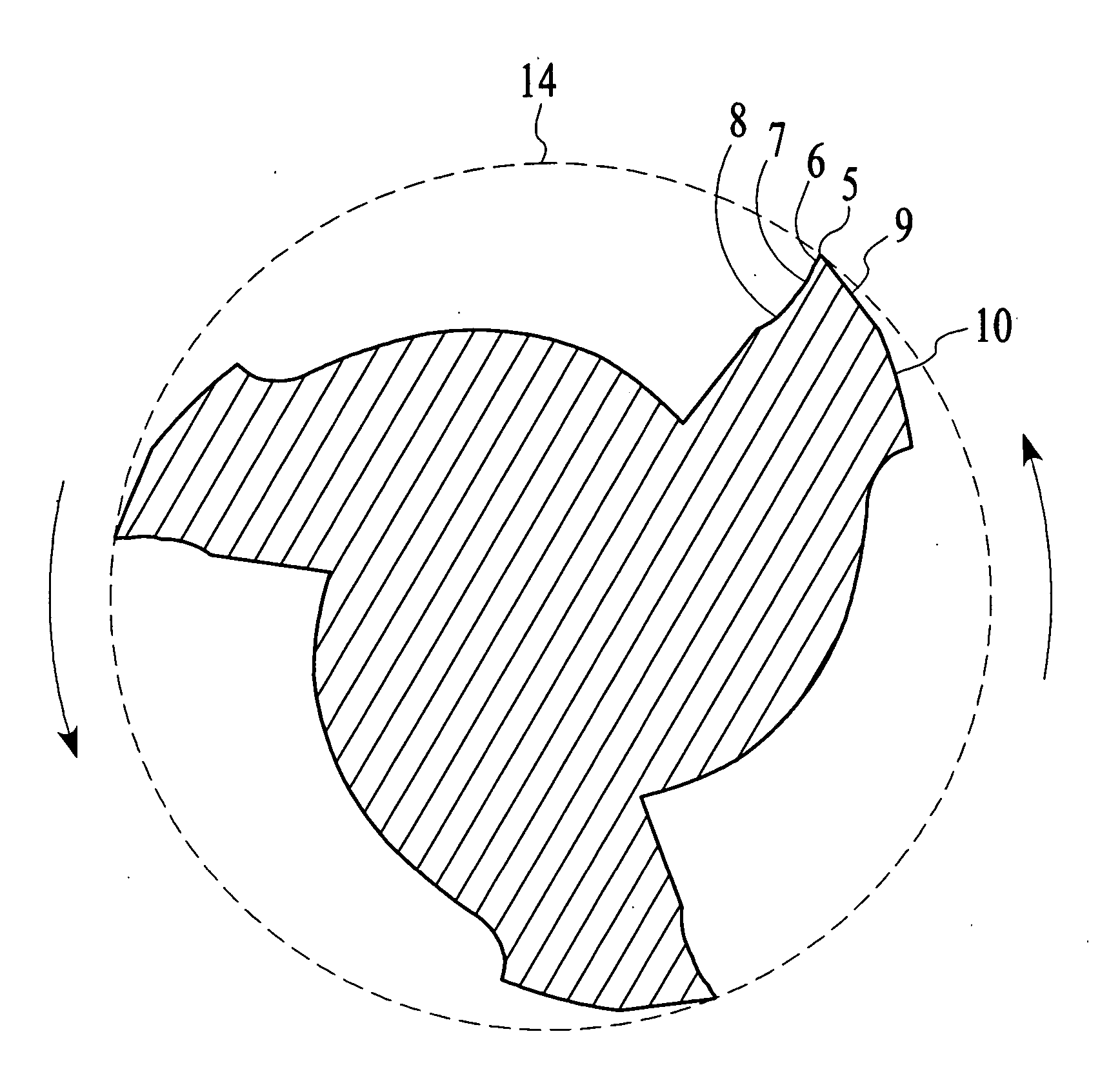
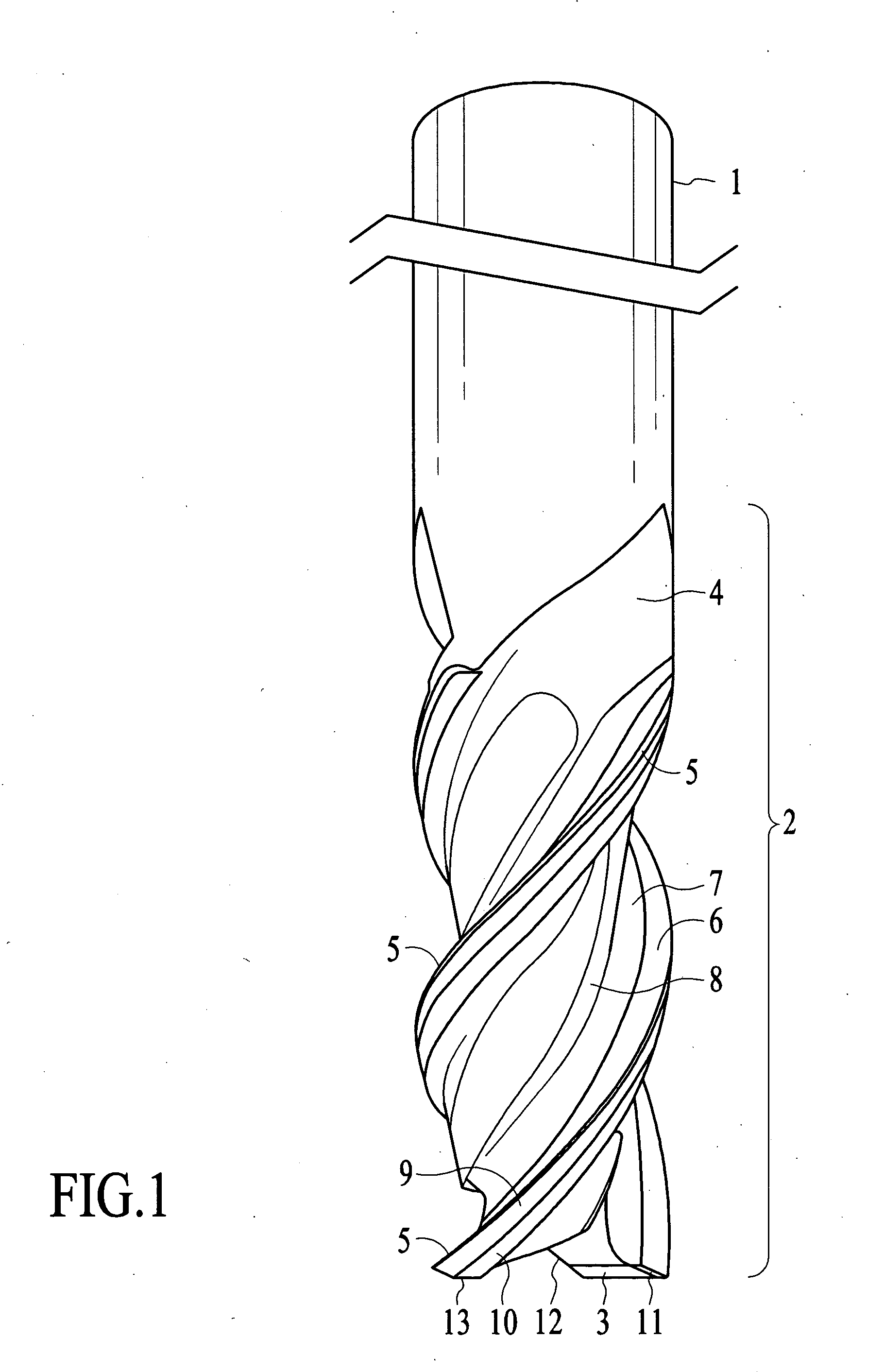
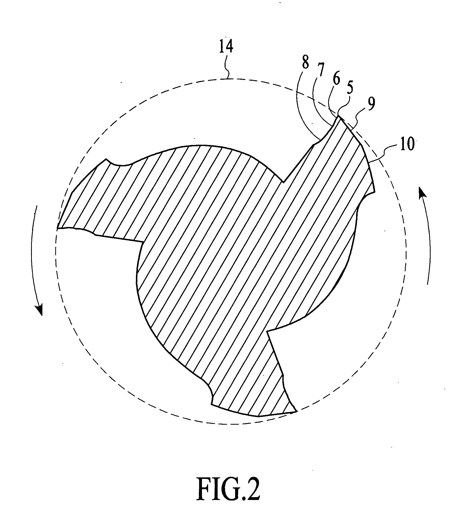
[0028] An improved helical, fluted single-end end mill is preferably made from ultra-fine micro grain tungsten carbide material with a cobalt content that varies from the top of the end mill to the bottom of the end mill. The end mill has a cylindrical shank 1, at least two helically fluted cutting teeth making up the helical cutting section of said end mill 2 said cutting teeth contain a tertiary tooth face 8, a secondary tooth face 7 and a primary tooth face 6.

[0029] Said cutting teeth also include a variable margin 5. In the prior art, the margin is the unrelieved part of the periphery of the land adjacent to the cutting edge. The margin width is the distance between the cutting edge and the primary relief see, 9, measured at a right angle to the cutting edge. Margin widths in the prior art are uniform from the terminal end of the cutting teeth on the margins entire length as it spirals upward toward the shank section of the end mill 15.

[0030] In the present invention, a variab...


PUM


Abstract

An end mill with a peripheral margin which increases in width from the terminal end of the tool to the shank portion of the tool. The end mill also has a tooth face made up of three tooth-face walls The depth of the tool face gradually decreases from the terminal end to the shank portion of the tool. The end mill also has an end cutting face which includes a flat, narrow land at the outmost region of the end cutting end. The end mill has chip breakers with rounded peripheral corners. The end mill can be made up of ultra-fine micro grain tungsten carbide with a cobalt content which varies throughout the length of the tool.

Description

FIELD OF THE INVENTION [0001] The present invention relates to the field of rotating end mills with multiple cutting surfaces. BACKGROUND OF THE INVENTION [0002] For decades, end mills have been used with rotating milling cutters to cut, shape and finish a wide variety of ferrous and non-ferrous metals and alloys. These end mills are typically made of hardened steel. [0003] U.S. Pat. No. 3,003,224 to Ribich discloses an end mill with two operating surfaces on the cutting face wall, as well as a primary and secondary tooth surface. According to Ribich, the secondary tooth surface on the cutting face of the end mill achieved a cleaner cut and a marked decrease of chip adherence to the cutting face surfaces. [0004] U.S. Pat. No. 5,049,009 to Beck discloses an improved rotary cutting end mill which includes an arcuate shaped circular land on the first relief wall which contacts the cutting edge, as well as a slightly angled cutting end. According to Beck, this improved end mill achieved...

Claims


Application Information

Patent Timeline
Patent Type & Authority Applications(United States)
IPC IPC(8): B23C5/10
CPCB23C5/10B23C2210/321B23C2210/445Y10T407/1946B23C2210/54B23C2222/28B23C2210/486
Inventor CALAMIA, GUY ALLEN
Owner CALAMIA GUY ALLEN
Why Eureka
Try Eureka