
Connection assembly

a technology of connecting parts and assembly, applied in the direction of supplementary fittings, rod connections, fastening means, etc., can solve the problems of not always simple to install, difficult to achieve attachment, and small parts such as bolts may be lost or dropped during fitting, so as to achieve the effect of simple use and attachmen

Inactive Publication Date: 2013-02-14
HUBCO AUTOMOTIVE
View PDF18 Cites 15 Cited by
  • Summary
  • Abstract
  • Description
  • Claims
  • Application Information

AI Technical Summary

Benefits of technology

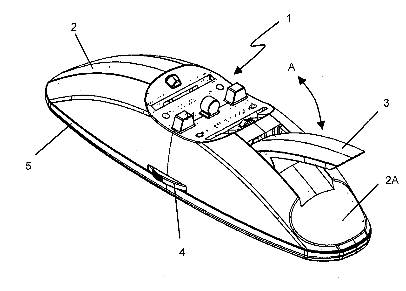
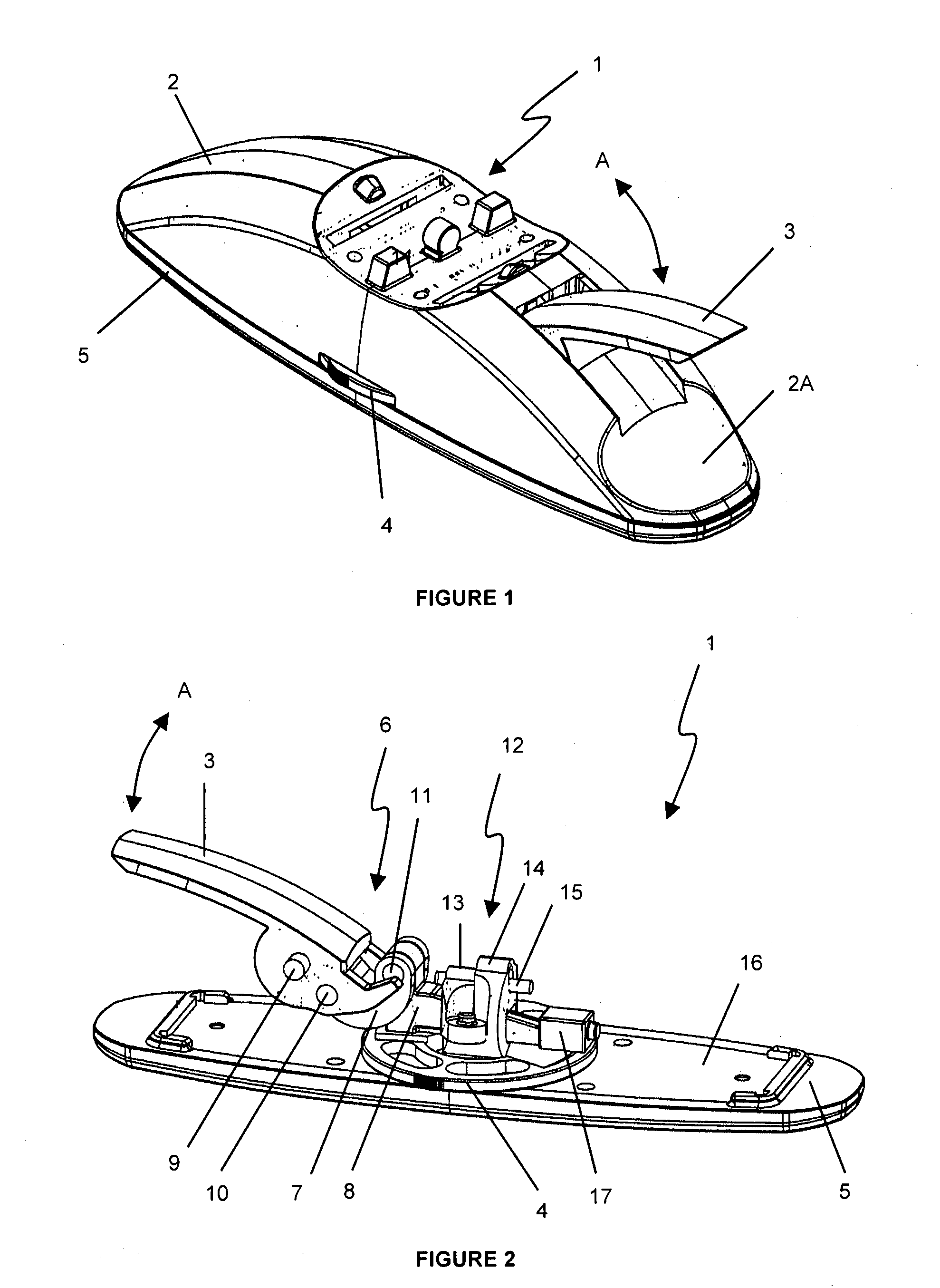
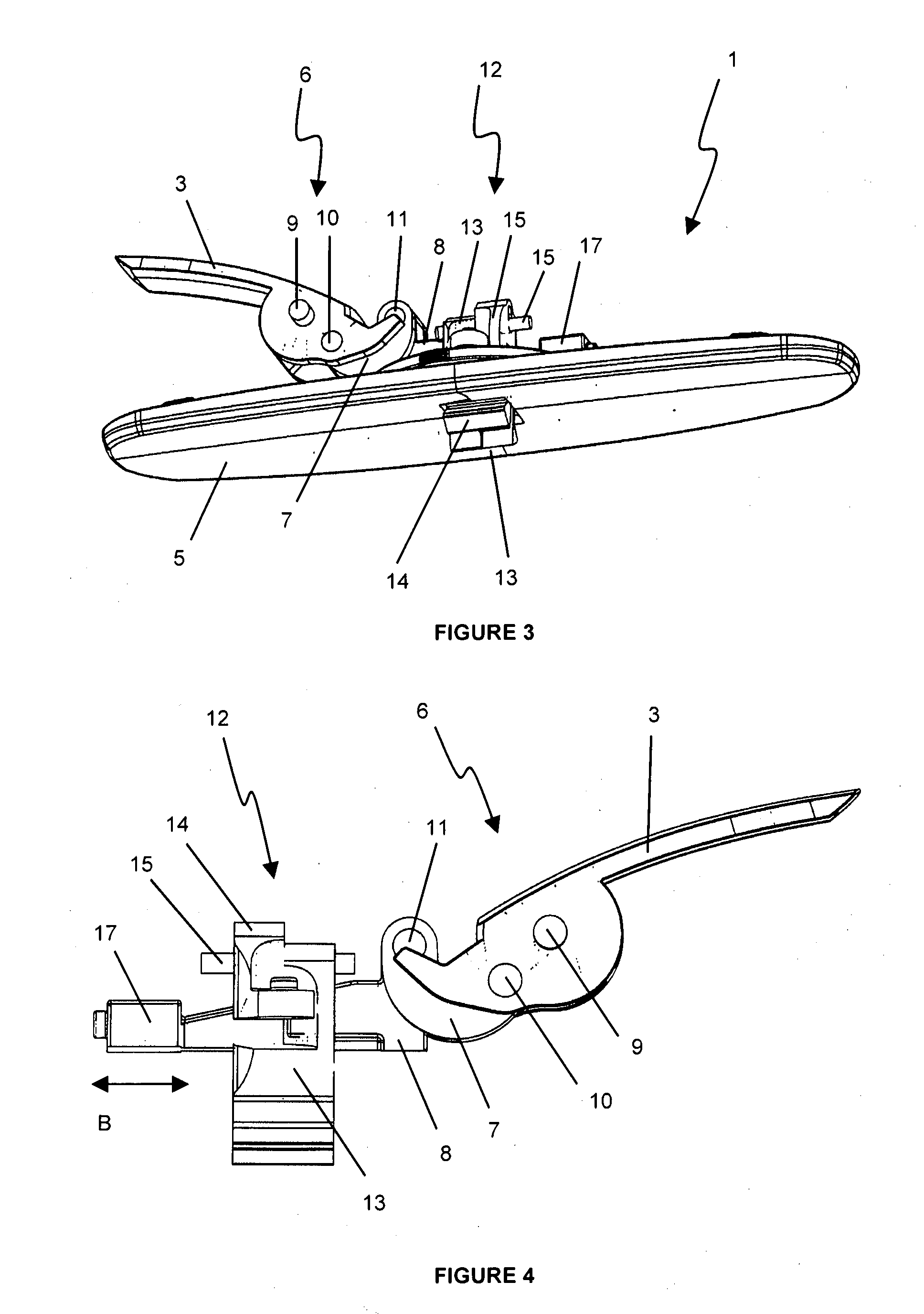
The patent describes a connection assembly for a roof rack that is easy to install, strong, and aerodynamic. The assembly includes a lever assembly and a jaw assembly connected by a wedged rod. The lever assembly includes a handle and an over center lever arrangement that translates rotational movement of the handle into lateral movement of the wedged rod. The wedged rod passes through an aperture in the jaws and is shaped to force the jaws apart. The assembly also includes a cover or enclosure that is aerodynamic and aesthetically pleasing. The connection assembly allows for easy adjustment of the jaws and is lightweight and strong. Its unique design features a disc cam that allows for tolerance variation and pre-adjustment for different sized channels. Overall, the connection assembly provides a simple and effective solution for roof rack installation.

Problems solved by technology

Whilst this design may meet the strength requirement, it is not always simple to install, particularly when the vehicle roof may be elevated and difficult to reach.
Further, attachment takes time to achieve due to the use of additional items e.g. tools and hard to access fixtures.
Still further, small parts such as bolts may be lost or dropped during fitting.
Also, as often the linking means are exposed on the vehicle roof, they may be weakened by environmental factors such as corrosion, they may provide wind resistance and therefore be noisy and reduce fuel efficiency.
Finally, they may reduce the aesthetics of the vehicle.

Method used


Image

  • Connection assembly
  • Connection assembly
  • Connection assembly

Examples


Embodiment Construction

[0046]The invention is now described with reference to a detailed description of an embodiment of the connection assembly mechanism and a related method of use. The example described refers to a connection assembly whereby the jaws of the assembly communicate with roof rack cross bars and the upper surface of the connection assembly communicates with an accessory rack via a slot and bolt arrangement. This should not be seen as limiting as the jaws may be used instead to attach the accessory rack (or directly attach accessory items) and two sets of opposing jaws may also be used without departing from the scope of the invention.

[0047]Referring to FIG. 1, a perspective view of the connection assembly, generally indicated by arrow 1 is illustrated. As shown, the assembly 1 includes a cover or enclosure 2 that has an elongated part ovoid shape designed to be aerodynamic so as to reduce wind resistance when fitted to a vehicle (not shown). The assembly 1 also includes a handle 3 that rev...


PUM


Abstract

A connection assembly is described that may be used to snap fit and lock together a channel containing member to other members. One embodiment described is use of the connection assembly to snap fit and lock together a roof rack accessory rack or item to fit roof rack crossbar on a vehicle.

Description

TECHNICAL FIELD[0001]The invention relates to a connection assembly. More specifically, the invention relates to an assembly and related method to link or connect a vehicle roof rack to another item such as an accessory rack or accessory item.BACKGROUND ART[0002]Vehicle roof racks are well known in the art with many products existing relating to a variety of different parts of various roof rack systems and the loads carried by such racks.[0003]A typical design of vehicle roof rack involves fitting of two cross bars across the roof of the vehicle at the front and rear of the vehicle roof. Various items may then be placed onto the cross bars for example, cycle holders, trade rack holders, kayak holders, fishing rod holders, surfboard holders and many other accessory racks or accessory items. The various accessory items may be directly attached to the crossbars or further forward facing racks used on which the accessory item(s) are mounted.[0004]Connecting the crossbars to the accessor...

Claims


Application Information

Patent Timeline
IPC IPC(8): B60R9/048
CPCB60R9/045F16B7/0473B60R9/058
Inventor HUBBARD, PETER DOUGLASROBERTSON, BRUCE JOHN
Owner HUBCO AUTOMOTIVE
Learn More