Pole Clamp

a technology of pole clamps and clamping rods, which is applied in the field of pole clamps, can solve the problems of not being able to adapt to be used with different diameter poles, and achieve the effects of reducing the effort a user has to spend, facilitating the user to turn the shaft, and being convenient to us

Inactive Publication Date: 2010-12-16
SMITHS MEDICAL ASD INC
View PDF11 Cites 51 Cited by
  • Summary
  • Abstract
  • Description
  • Claims
  • Application Information

AI Technical Summary

Benefits of technology

[0006]The threaded shaft has a contact end that faces the V-shaped leg of the clamp member and a knob at its other end that makes it easier for the user to turn the shaft, when the actuator is positioned to guide the movement of the threaded shaft. The actuator mechanism may also be moved to a second position such that the threaded guide is moved away from the threads of the screw or the threaded outer circumferential surface of the shaft, to thereby enable the threaded shaft to freely slide bidirectionally through the channel.
[0008]The pole clamp of the instant invention therefore is a device that is simple both in terms of its manufacture and use, that reduces the efforts a user has to spent to both attach and remove the clamp from a pole, that is adaptable to be used with poles of different diameters, and that is easy and inexpensive to manufacture.

Problems solved by technology

The problem with these clamps is the need to twist or rotate the threaded shaft through multiple turns in order to adjust the clamp between the different sized poles.
Also, the need to provide multiple sized clamps to cover all of the poles that may be used in a hospital environment can be a problem for the user if she does not have the correct clamp, and for the manufacturer, due to the need to manufacture different clamps to fit onto the different sized poles.
However, those pole clamps are either not adaptable to be used with different diameter poles, or are designed to require a myriad of parts.

Method used


Image

  • Pole Clamp
  • Pole Clamp
  • Pole Clamp

Examples


Embodiment Construction

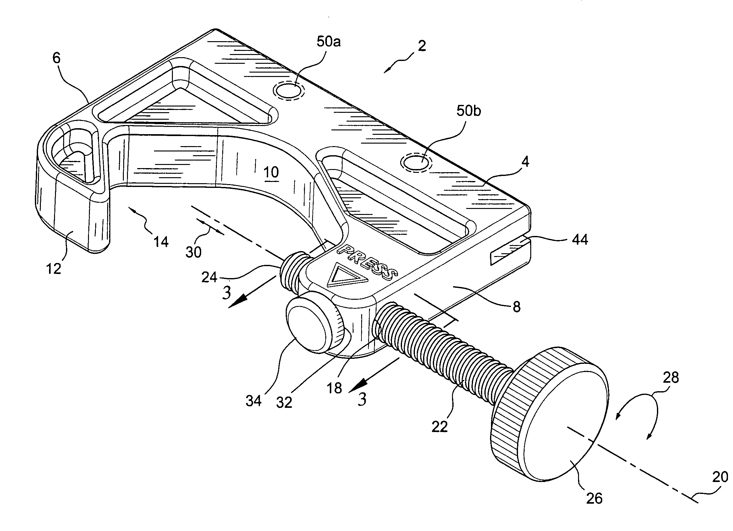
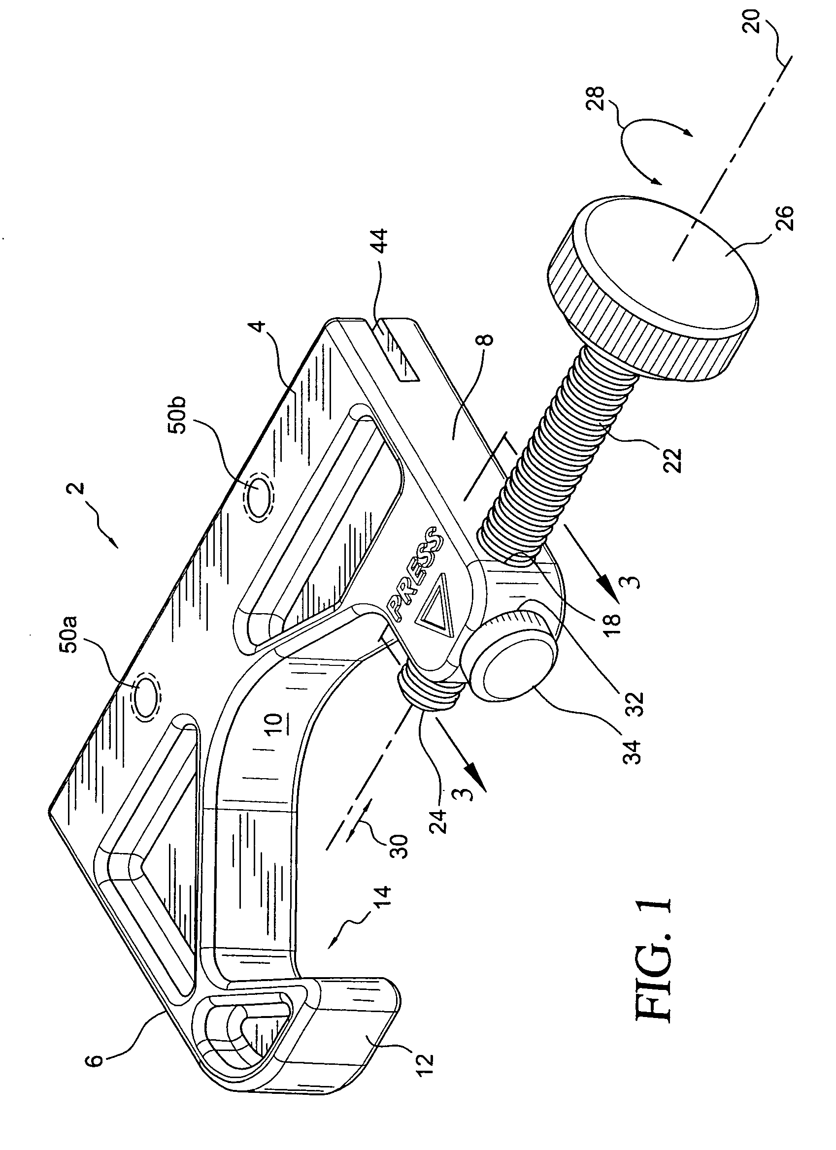
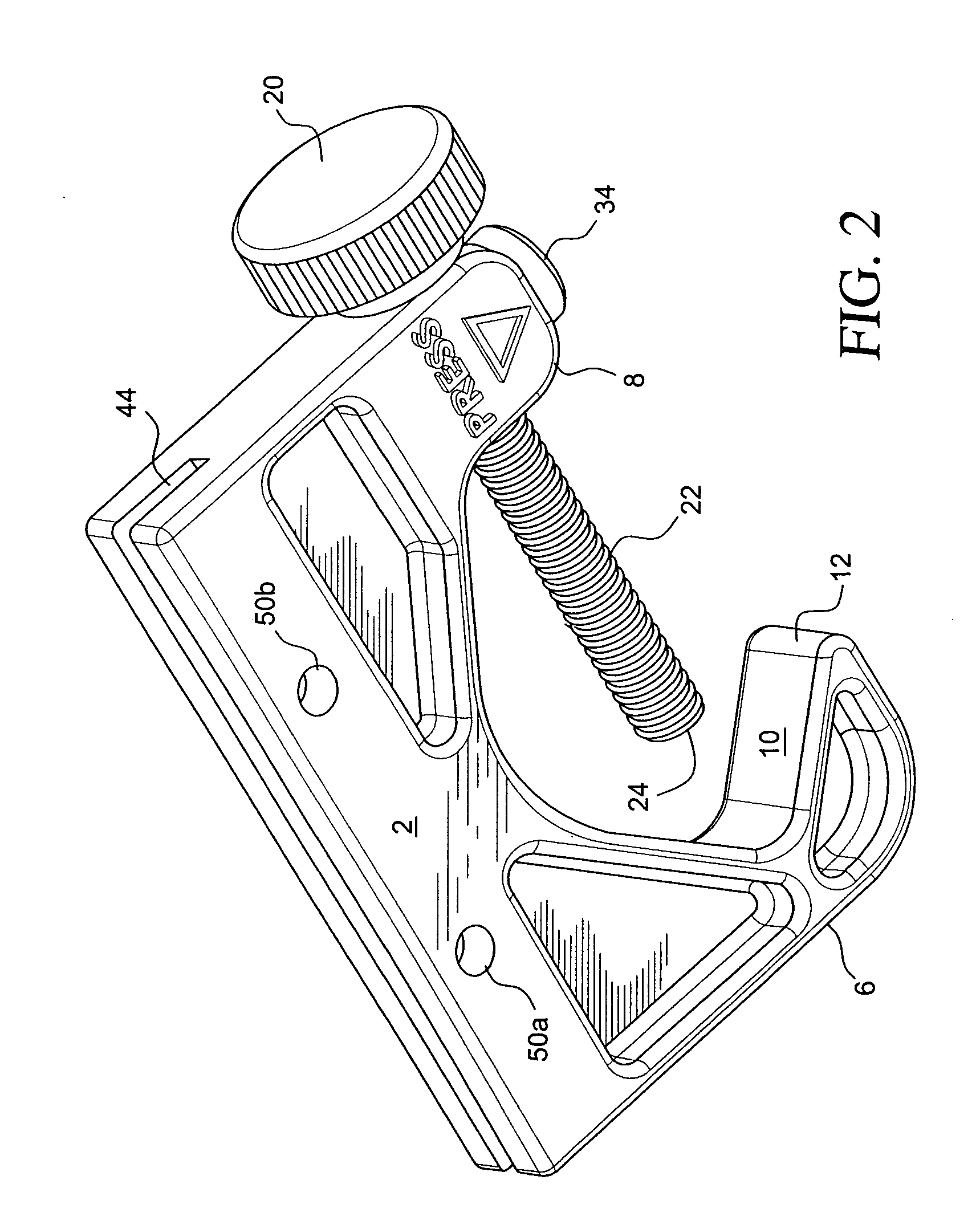
[0022]With reference to FIG. 1, a pole clamp 2 of the instant invention is shown to have a substantially U-shaped body or member 4 with a first leg 6 and a second leg 8 extending from body 4. For the exemplar pole clamp 2 shown, member 4 has an elongated body with a concave interior wall 10 that extends to leg 6, which has a finger portion 12 extending outwardly, so that leg 6 is substantially V-shaped, per shown by directional arrow 14 pointing to the valley of leg 6. So configured, the interior wall 10 of leg 6 is adapted to grippingly contact a first side of the circumferential surface of a pole, such as pole 16 shown in FIG. 5, and firmly hold the pole were a force applied against the opposite side surface of the pole. It should be noted that the particular shape of leg 6 is not of utmost import to the invention so long as it is understood that leg 6 may have any interior wall adaptable to hold a side surface of a pole placed between legs 6 and 8.

[0023]Extending from member 4 at...


PUM


Abstract

A pole clamp has two legs wherebetween poles of different diameters may be positioned. One of the legs is configured to grip one side surface of the pole. The other leg of the clamp member has a channel through which a threaded shaft is movable along a longitudinal axis toward the one leg. Also formed in the other leg is a bore orthogonally to the channel. A guide that may be in the form of a half nut is movable within the bore, with the threaded surface of the half nut being in a threaded relationship with the threads of the shaft, when the guide is in a first position, so that the shaft is movable along the axis when it is turned. The guide is movable to a second position to disengage its threaded surface from the shaft. When thus disengaged, the shaft is movable bidirectionally along the axis by simple push and pull movements. A second embodiment of the pole clamp utilizes a yoke slider guide having two arms with a narrow gap and a wider gap between the two arms.

Description

FIELD OF THE INVENTION [0001]The present invention relates to clamps and more particularly to a pole clamp that can readily attach a medical device to poles of different diameters.BACKGROUND OF THE INVENTION [0002]Poles for attaching devices come in various sizes, for example, 0.5 inch and 1.5 inch. Thus, for the different diameter poles to be used in hospitals, different U-shaped frames each with a simple screw-threaded shaft mounted to one arm are used to attach medical instruments to poles of different diameters. Each pole is usually fitted between the two arms of the clamp and the knob on the screw is rotated to bring the opposite end of the shaft to bear on the pole and clamp it firmly against the inside of the opposite arm.[0003]The problem with these clamps is the need to twist or rotate the threaded shaft through multiple turns in order to adjust the clamp between the different sized poles. Also, the need to provide multiple sized clamps to cover all of the poles that may be...

Claims


Application Information

Patent Timeline
Patent Type & Authority Applications(United States)
IPC IPC(8): A47B96/06
CPCA61G13/101A61M5/1415A61M5/1417B25B5/10B25B5/101F16B2/065F16B37/0878
Inventor PATZER, CHARLES R.
Owner SMITHS MEDICAL ASD INC
Why Eureka
Try Eureka