Draw extending archery system

a drawing system and archery technology, applied in the field of archery, can solve the problems of limited user capability, limited draw force, single draw compound bows have their own limits, etc., and achieve the effects of shifting energy output limitations, greater arrow speed, and longer effective draw length

Inactive Publication Date: 2014-11-25
D BOW LLC
View PDF10 Cites 17 Cited by
  • Summary
  • Abstract
  • Description
  • Claims
  • Application Information

AI Technical Summary

Benefits of technology

[0008]The above-mentioned and other problems are addressed by a draw extending system that enables a user to draw a bow's draw string multiple times to store energy in a flexible limb. Through successive charging strokes of the draw string, the draw extending system stores successive amounts of energy in the flexible limbs and thusly shifts energy output limitations from user capability to strength of materials and mechanics. Accordingly, the draw extending system enables a given user to achieve greater arrow speeds and / or use heavier projectiles than their physical capability previously allowed.
[0009]In one embodiment, the draw extending system effectively extends the length of the draw past the previous limit, which was a user's wingspan. Consider a bow with a manageable draw weight, such as 70 pounds, and a draw length of 30 inches (ignoring brace height for simplicity). Embodiments of the draw extending system include a transmission that, while keeping the actual draw length and draw weight the same for the user, enables multiple inputs (e.g., several 30 inch draws) on the draw string to create a longer effective draw length (e.g., 90 inches) for storing more energy. For example, one embodiment of the transmission may divide an effective draw length over three draws to increase storage of energy.
[0010]In another embodiment, the draw extending system enables a given user to use a bow with a heavier draw weight. Consider, again, the above example bow with a draw weight of 70 pounds and an effective draw length of 90 inches. Embodiments of the draw extending system include a transmission with a reduction mechanism that, while shortening effective draw length (e.g., down from 90 inches), increases leverage over the flexible limb when drawing the bow. Increasing leverage over the limb with the reduction mechanism decreases the effective draw weight felt by the user. Thus, for example, one embodiment of the transmission may reduce actual draw weight (e.g., down from 70 pounds per draw) to decrease required user effort and retain storage of energy through addition of draws.
[0011]In one embodiment, a transmission of a bow transfers energy received through a number of inputs into one or more flexible limbs. In one embodiment, the transmission transfers energy through a reduction mechanism. Embodiments of the reduction mechanism may transfer power directly or modify leverage of its input over its output to increase or decrease user effort required for compression of the one or more limbs. At the end of each charging stroke, the transmission engages to prevent release of energy from the limbs. Once an appropriate number of charging strokes are completed, the energy in the limbs may be released. In one embodiment, the transmission causes the flexible limbs to release substantially the sum of energy stored over the inputs into a string of the bow. Embodiments of a bow may use one or more transmissions for compressing flexible limbs coupled to a riser.

Problems solved by technology

Though an improvement over historical designs, the single draw compound bow has its own limits.
Generally, as the energy stored in a bow is equal to the force of the draw multiplied by the distance of the draw, energy output is limited by user capability.
For example, draw force is limited by the strength of the user and draw distance is limited by the reach of the user, both of which have upper limits.
Through successive charging strokes of the draw string, the draw extending system stores successive amounts of energy in the flexible limbs and thusly shifts energy output limitations from user capability to strength of materials and mechanics.
Increasing leverage over the limb with the reduction mechanism decreases the effective draw weight felt by the user.

Method used


Image

  • Draw extending archery system
  • Draw extending archery system
  • Draw extending archery system

Examples


example method

of Operation

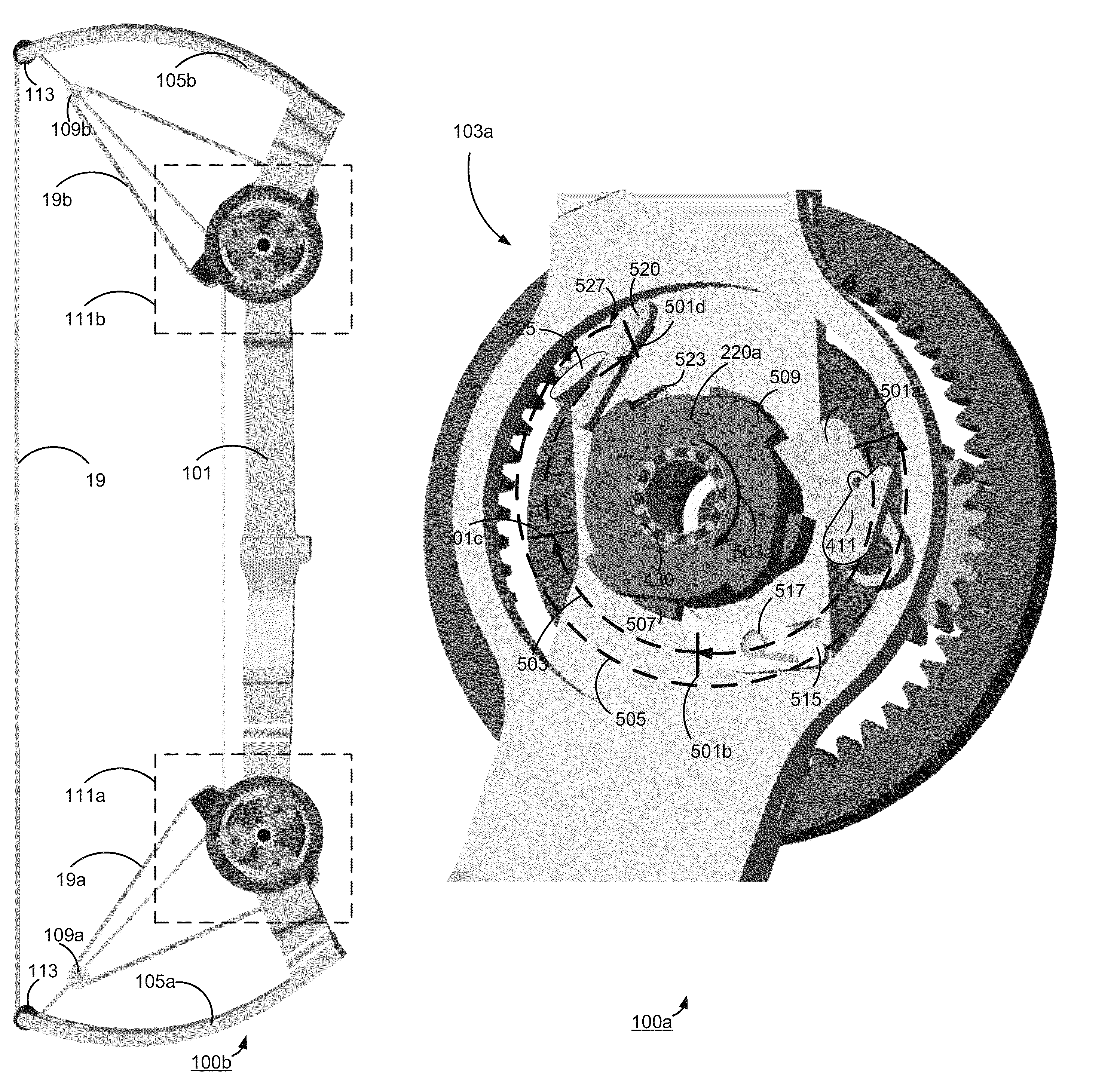
[0040]FIG. 2a is a schematic diagram illustrating a bow, including a transmission, being drawn from a left-side view 100a, according to one embodiment. As shown, the lower 103a and upper 103b left-side transmission components include multiple components themselves. In some embodiments, configuration of the lower 103a transmission components is substantially mirrored across the axis of the draw 210 for configuring arrangement of the upper 103b transmission components.

[0041]The draw string 18 is coupled to lower 210a and upper 210b main cams and may be drawn 201 from a rest position to a fully drawn position. The main cams 210 are eccentric cams, pulleys or wheels which rotate around a central axis and house the draw string 18. As the main cams 210 rotate, they let out or reel in the draw string 18. FIG. 2a illustrates the directions of rotation of the respective main cams 210a, 210b during the draw 201.

[0042]The main cams 210 are operatively coupled to the respective driv...


PUM


Abstract

A draw extending archery system enables a user to draw a draw string multiple times to store energy. Embodiments of the system include a transmission that operatively engages the draw string and a flexible limb. From an initial rest position, the user initiates a charging stroke on the draw string. During a first charging stroke, the transmission engages to store energy during the draw. At the end of the charging stroke, the transmission engages to prevent release of stored energy. The transmission also disengages the draw string to enable a subsequent charging stroke from an intermediate rest position. From a final rest position, the user initiates a firing stroke on the draw string. At the end of the firing stroke, the transmission couples the draw string and the flexible limb to release stored energy through the draw string.

Description

CROSS REFERENCE TO RELATED APPLICATIONS[0001]This application claims the benefit of U.S. Provisional Application No. 61 / 504,922, filed Jul. 6, 2011, which is incorporated by reference herein in its entirety.BACKGROUND[0002]1. Field of Art[0003]The disclosure generally relates to the field of archery and more specifically to a system for storing energy through multiple draw strokes.[0004]2. Background Information[0005]Ever since the bow and arrow first appeared in the late Paleolithic period, man has sought to improve its performance. Relatively speaking, however, operation of the modern bow is similar to that of historic specimens found in Holmegaard, Denmark, dating back over 8,000 years. The historical bow itself evolved into various forms such as the recurve bow, composite bow and other designs as makers sought to improve efficiency, arrow speed, accuracy and other performance characteristics. Historical development of the bow reached its peak in both complexity and power in the ...

Claims


Application Information

Patent Timeline
Patent Type & Authority Patents(United States)
IPC IPC(8): F41B5/10
CPCF41B5/10F41B5/0094F41B5/1403
Inventor DEBOLE, ROBERT
Owner D BOW LLC
Why Eureka
Try Eureka