MEMS device anchoring

a technology of mems device and anchoring device, which is applied in the direction of relays, generators/motors, instruments, etc., can solve the problems of switch or cantilever, mems device to fail,

Active Publication Date: 2014-10-09
QORVO US INC
View PDF8 Cites 18 Cited by
  • Summary
  • Abstract
  • Description
  • Claims
  • Application Information

AI Technical Summary

Benefits of technology

[0007]The present invention generally relates to a MEMS device that is anchored using the layer that is deposited to form the cavity sealing layer and / or with the layer that is deposited to form the pull-off electrode. The switching element of the MEMS device will have a flexible or movable portion that moves between two electrodes. The switching element will also have a fixed or anchor portion that is electrically coupled to ground. The layer that is used to seal the cavity in which the switching element is disposed can also be coupled to the fixed or anchor portion of the switching element to anchor the fixed or anchor portion within the cavity. Additionally, the layer that is used to form one of the electrodes may be used to provide additional leverage for anchoring the fixed or anchor portion within the cavity. In either situation, the movement of the flexible or movable portion is not hindered.

Problems solved by technology

One of the issues found in shrinking MEMS devices to the scale of less than a few micrometers is the ability of the switch or cantilever to be pulled into contact with an electrode and then released back to its original state repeatedly and reliably.
Due to the length of the cantilever or switch that is necessary to create the flexibility of the cantilever or switch, the switch or cantilever may break at the anchor portion and cause the MEMS device to fail.

Method used


Image

  • MEMS device anchoring
  • MEMS device anchoring
  • MEMS device anchoring

Examples


example

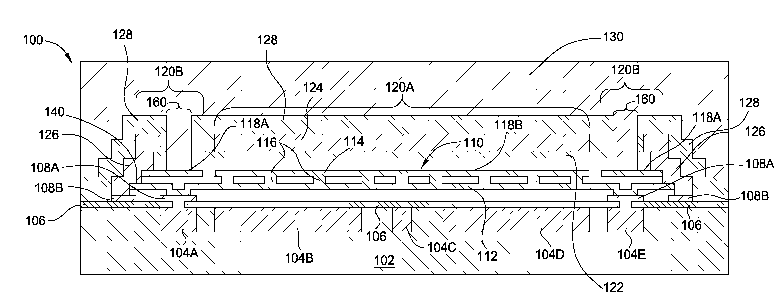
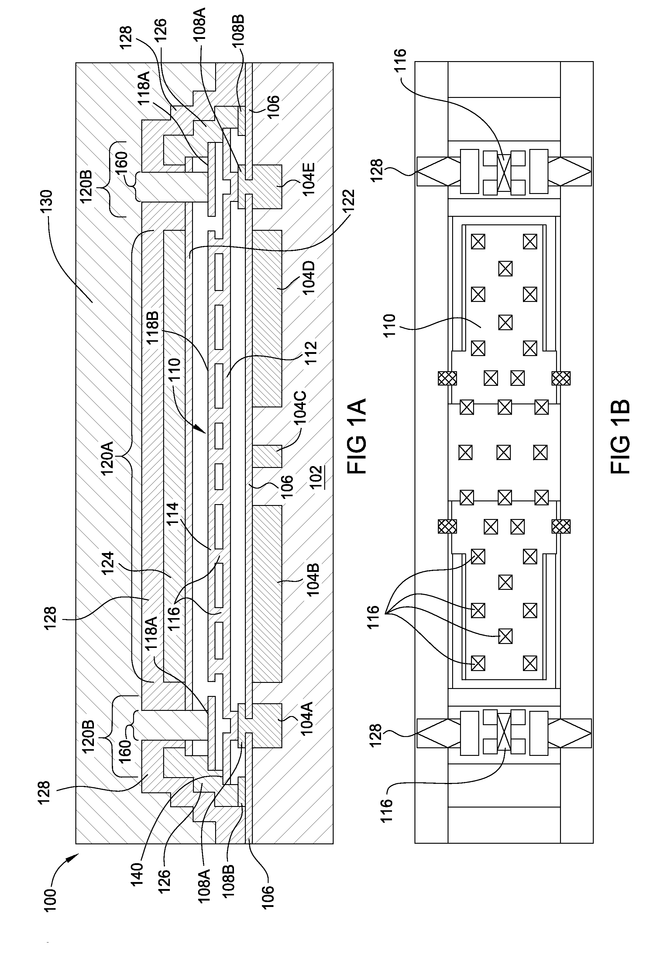
[0046]When a debonded area is subject to stress, an out-of-plane deflection could occur (commonly called buckling). The threshold level at which buckling occurs is a function of: (a) the geometry and size of the debonded area (free-standing cap), (b) the material & thickness of the cap, (c) the stress in the cap, (d) the Temperature change the cap will see and (e) the anchoring.

[0047]The threshold at which buckling could occur as well as the post-buckling response can be easily calculated for two simple geometry cases: a strip of uniform width and a circular patch. In the case of a strip of uniform width, the compressive level required to induce an out-of-plane deflection in a film with debonded zone of size am is:

σm=-π2Ef_12(hfam)2withEf_=Ef1-υf2

[0048]Where Ef is the elastic modulus, uf is Poisson ratio, am is the debonded zone width and hf is the film thickness. In the case of a circular patch, the relationship is approximated by the following:

σm=-1.2235Ef_(hfam)2

[0049]Assuming a ...


PUM

PropertyMeasurementUnit
temperatureaaaaaaaaaa
widthaaaaaaaaaa
widthaaaaaaaaaa

Abstract

Embodiments of the present invention generally relate to a MEMS device that is anchored using the layer that is deposited to form the cavity sealing layer and / or with the layer that is deposited to form the pull-off electrode. The switching element of the MEMS device will have a flexible or movable portion and will also have a fixed or anchor portion that is electrically coupled to ground. The layer that is used to seal the cavity in which the switching element is disposed can also be coupled to the fixed or anchor portion of the switching element to anchor the fixed or anchor portion within the cavity. Additionally, the layer that is used to form one of the electrodes may be used to provide additional leverage for anchoring the fixed or anchor portion within the cavity. In either situation, the movement of the flexible or movable portion is not hindered.

Description

BACKGROUND OF THE INVENTION[0001]1. Field of the Invention[0002]Embodiments of the present invention generally relate to a micro-electromechanical (MEMS) device that is anchored using the layers that are used to form both the sealing layer and the pull-off electrode.[0003]2. Description of the Related Art[0004]As the size of semiconductors continues to shrink, so does the MEMS devices that are coupled to the semiconductors. MEMS devices may be used as miniature relay switches, capacitance switches, non-volatile memory elements and for many more applications. The MEMS devices have a switch or cantilever that moves between at least two positions to either permit or deny a current from flowing through the switch.[0005]MEMS devices are made using similar processing steps to those found in semiconductor foundries and therefore can be manufactured cost effectively on a wafer scale. One of the issues found in shrinking MEMS devices to the scale of less than a few micrometers is the ability...

Claims


Application Information

Patent Timeline
Patent Type & Authority Applications(United States)
IPC IPC(8): B81B7/00
CPCB81B7/00B81C1/00039H01H59/0009B81B2201/016B81B2203/0307B81C2203/0136H01G5/16Y10T29/49105
Inventor VAN KAMPEN, ROBERTUS PETRUSRENAULT, MICKAELJOSHI, VIKRAMKNIPE, RICHARD L.UNAMUNO, ANARTZ
Owner QORVO US INC
Why Eureka
Try Eureka