
Hand held surgical handle assembly, surgical adapters for use between surgical handle assembly and surgical end effectors, and methods of use

a technology for surgical handle and adapter, which is applied in the field of hand-held powered surgical devices, surgical adapters and/or adapter assemblies, and can solve the problems of end effectors not being compatible with surgical devices and/or handle assemblies

Active Publication Date: 2012-10-04
TYCO HEALTHCARE GRP LP
View PDF4 Cites 943 Cited by
  • Summary
  • Abstract
  • Description
  • Claims
  • Application Information

AI Technical Summary

Benefits of technology

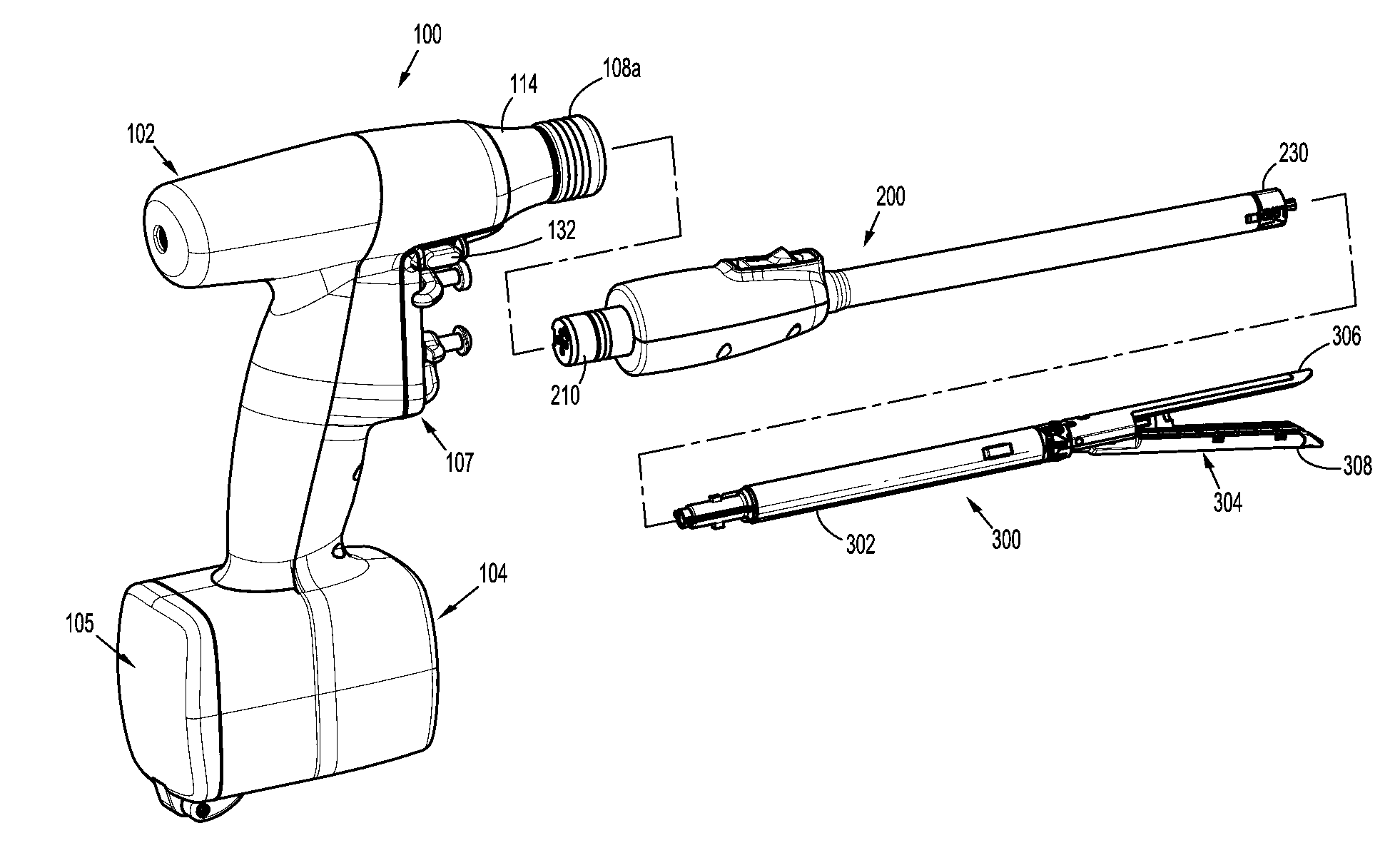
[0032]According to yet another aspect of the present disclosure, an adapter assembly is provided for selectively interconnecting a surgical end effector that is configured to perform a function and a surgical device that is configured to actuate the end effector, the end effector including at least one axially translatable drive member, and the surgical device including at least one rotatable drive shaft. The adapter assembly includes a housing configured and adapted for connection with the surgical device and to be in operative communication with each of the at least one rotatable drive shaft of the surgical device; an inner housing tube having a proximal end supported by the housing, the inner housing tube defining an internal cavity and at least one aperture opening into the cavity; a distal coupling assembly disposed at a distal end of the inner housing tube, wherein the distal coupling assembly is configured to selectively connect with the end effector; at least one drive converter assembly for interconnecting a respective one of the at least one rotatable drive shaft of the surgical device and one of the at least one axially translatable drive member of the end effector, wherein the at least one drive converter assembly is at least partially disposed within the cavity of the inner housing tube; and a plurality of seals disposed between the inner housing tube and the at least one drive converter assembly so as to prevent ingress of fluid into the cavity of the inner housing tube.

Problems solved by technology

As such, these end effectors are not compatible with surgical devices and / or handle assemblies that use a rotary motion to deliver power or the like.

Method used


Image

  • Hand held surgical handle assembly, surgical adapters for use between surgical handle assembly and surgical end effectors, and methods of use
  • Hand held surgical handle assembly, surgical adapters for use between surgical handle assembly and surgical end effectors, and methods of use
  • Hand held surgical handle assembly, surgical adapters for use between surgical handle assembly and surgical end effectors, and methods of use

Examples


Embodiment Construction

[0073]Embodiments of the presently disclosed surgical devices, and adapter assemblies for surgical devices and / or handle assemblies are described in detail with reference to the drawings, in which like reference numerals designate identical or corresponding elements in each of the several views. As used herein the term “distal” refers to that portion of the adapter assembly or surgical device, or component thereof, farther from the user, while the term “proximal” refers to that portion of the adapter assembly or surgical device, or component thereof, closer to the user.

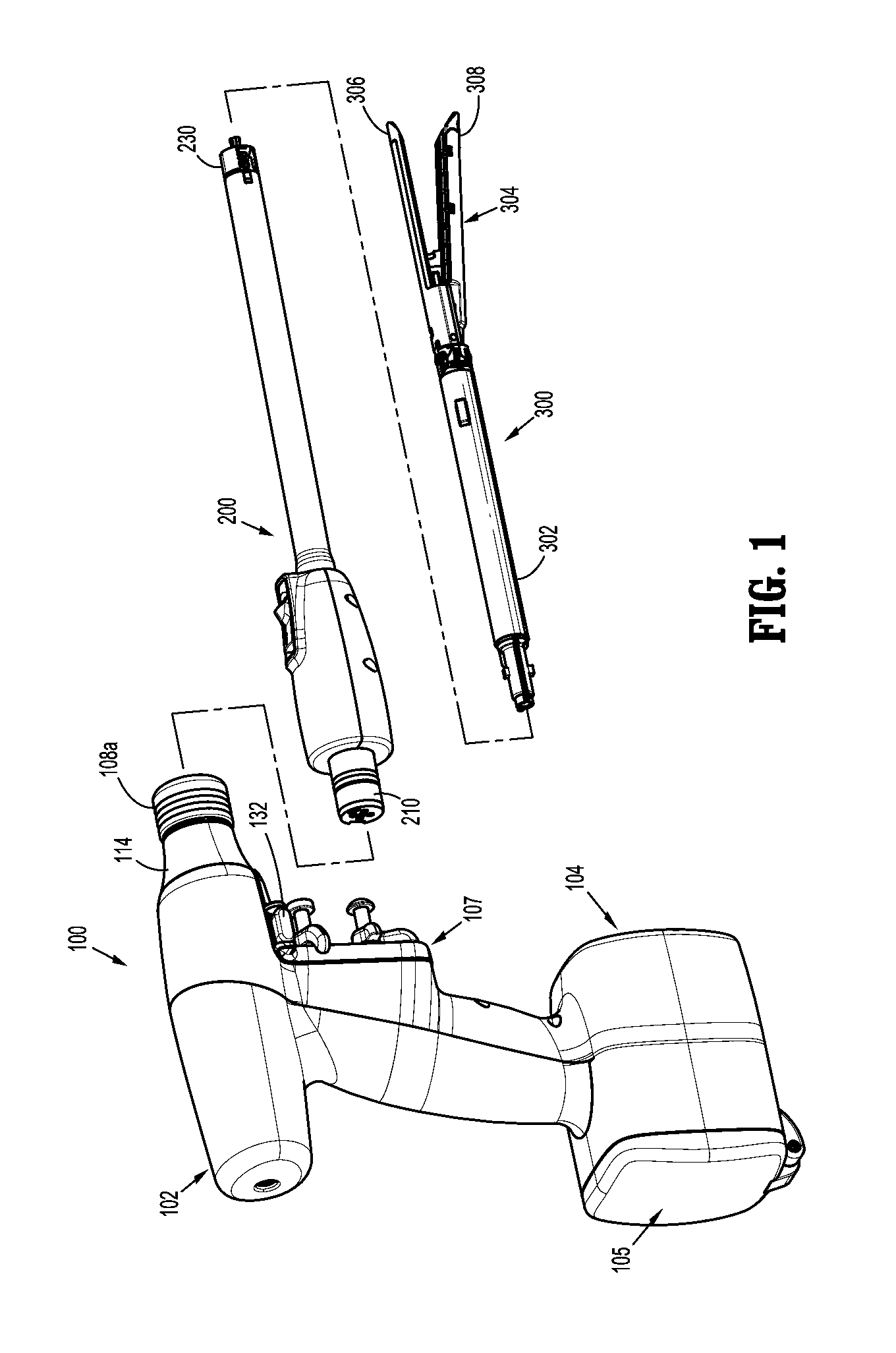
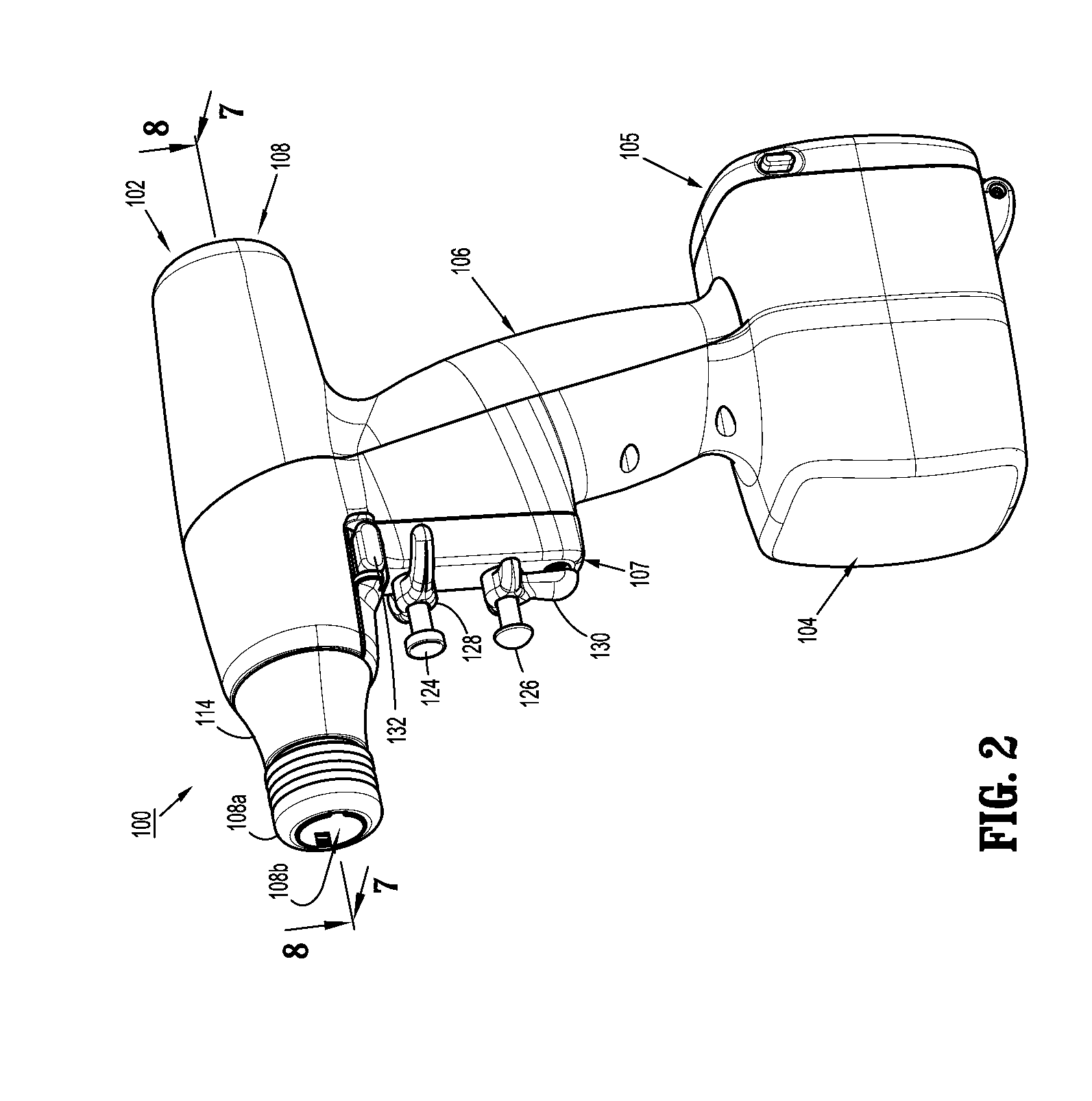
[0074]A surgical device, in accordance with an embodiment of the present disclosure, is generally designated as 100, and is in the form of a powered hand held electromechanical instrument configured for selective attachment thereto of a plurality of different end effectors that are each configured for actuation and manipulation by the powered hand held electromechanical surgical instrument.

[0075]As illustrated in FIG....


PUM


Abstract

Adapter assemblies are provided for selectively interconnecting a surgical end effector that is configured to perform at least a pair of functions and a surgical device that is configured to actuate the end effector, wherein the end effector includes a first axially translatable drive member and a second axially translatable drive member, and wherein the surgical device includes a first rotatable drive shaft and a second rotatable drive shaft.

Description

CROSS REFERENCE TO RELATED APPLICATION[0001]The present application is a Continuation-in-Part Application claiming the benefit of and priority to U.S. patent application Ser. No. 13 / 331,047, filed on Dec. 20, 2011, which is a Continuation-in-Part Application claiming the benefit of and priority to U.S. patent application Ser. No. 12 / 946,082, filed on Nov. 15, 2010, which claims the benefit of and priority to each of U.S. Provisional Application Ser. No. 61 / 308,045, filed on Feb. 25, 2010, and U.S. Provisional Application Ser. No. 61 / 265,942, filed on Dec. 2, 2009, the entire content of each of which being incorporate herein by reference.[0002]U.S. patent application Ser. No. 13 / 331,047, filed on Dec. 20, 2011, is a Continuation-in-Part Application claiming the benefit of and priority to U.S. patent application Ser. No. 12 / 758,900, filed on Apr. 13, 2010, which is a Continuation-in-Part Application claiming the benefit of and priority to U.S. patent application Ser. No. 12 / 622,827, f...

Claims


Application Information

Patent Timeline
Patent Type & Authority Applications(United States)
IPC IPC(8): A61B17/00
CPCA61B17/072A61B17/115A61B2017/0023A61B2017/00473A61B2017/00398A61B2017/00464A61B2017/00371A61B2017/00734A61B90/70A61B2017/2903A61B2017/2948A61B17/285A61B17/29A61B2017/0046A61B2017/2901
Inventor ZEMLOK, MICHAELWILLIAMS, RYANMARCZYK, STANISLAWPATEL, NIHIRCHOWANIEC, DAVID
Owner TYCO HEALTHCARE GRP LP
Learn More