Play-free rotary mounting

a rotary mounting and rotary technology, applied in the direction of instruments, mechanical devices, optical elements, etc., can solve the problems of insufficient space, insufficient wall thicknesses available on the housing and in the drive roll, and the inability to adjust, so as to achieve the effect of low production cost of mounting

Inactive Publication Date: 2006-05-23
LEICA GEOSYSTEMS AG
View PDF7 Cites 5 Cited by
  • Summary
  • Abstract
  • Description
  • Claims
  • Application Information

AI Technical Summary

Benefits of technology

[0009]The invention was therefore based on the object of providing a mounting which can be adjusted absolutely without play, axially and radially, and at the same time run freely for a drive roll for an adjusting mechanism under very restricted space conditions. Additionally, the production costs of the mounting should be as low as possible.
[0014]In the event of different vertex diameters for the annular grooves and the bearing shells, the latter in each case bear firmly with only one flank in the associated annular groove. Following insertion of the balls into the bearing shells, the respective free flank of the bearing shell can deform resiliently under the pressure from the balls as the drive roll is clamped in the axial direction. In this case, the free-running ability of the balls is not hampered and, at the same time, any play is removed from the mounting. The means of fixing the drive roll in the axial direction therefore serves at the same time to adjust the play of the mounting. Here, the drive roll is centered in its end mounting and additionally also in the radial direction. If the end faces are mounted on both sides, frictional forces with respect to the cylindrical body can be eliminated.
[0015]In the event of identical vertex diameters for the annular grooves and the bearing shells, the bearing shells bear with both flanks on the flanks of the annular groove. Because of the requisite greater opening angle of the bearing shells with respect to the opening angle of the annular grooves, this contact is annular. As the drive roll is clamped in the axial direction, the bearing shells are pressed further into the annular grooves by the pressure of the balls, reducing their opening angle and displacing the bearing ring. This produces likewise a mounting for the drive roll that is free of play, radially and axially, and runs easily.

Problems solved by technology

In contrast, sliding bearings set without play are not free-running and have temperature-dependent and load-dependent torque differences and, as a result, their ability to be adjusted is considerably restricted.
For the installation of conventional ball bearings, the wall thicknesses available on the housing and in the drive roll are frequently inadequate.
In addition, in fine instrument making there is often inadequate space available for the installation of special prestressing means for setting bearing play.

Method used


Image

  • Play-free rotary mounting
  • Play-free rotary mounting
  • Play-free rotary mounting

Examples


Embodiment Construction

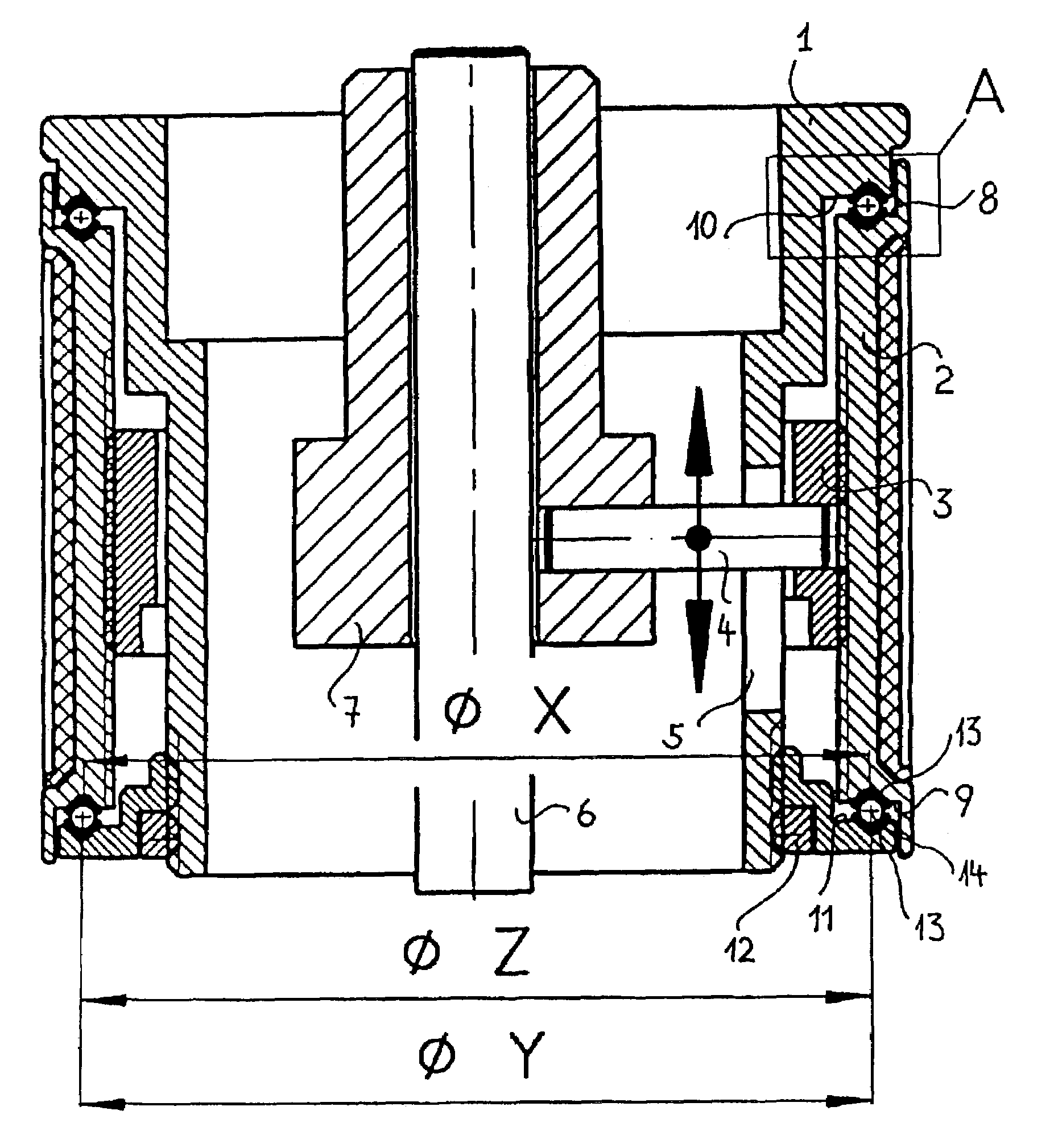
[0022]In FIG. 1, a drive roll 2 is rotatably mounted on a cylindrical body 1. The body 1 is, for example, part of the hinge bridge of a pair of binoculars, and the drive roll 2 is the drive knob for setting the focus. For this purpose, a screw ring 3 is mounted in a thread in the drive roll 2. Inserted into the screw ring 3 is a pin 4 which is guided in a longitudinal slot 5 in the body 1. A sleeve 7, which is coupled to the pin 4, is mounted such that it can be displaced longitudinally on a stationary shaft 6 belonging to the body 1. In the event of rotation of the drive roll 2, the sleeve 7 is displaced in the direction of the arrow on the shaft 6 in a known way. Adjusting elements, not further shown, belonging to the pair of binoculars, are coupled to the sleeve 7. The transmission of the adjustment forces from the drive roll 2 is to take place without play and without any backlash at the points of reversal. As a result of the mounting of the drive roll 2, no additional frictiona...


PUM


Abstract

A play-free rotary mounting for a drive roll held on stop surfaces in the axial direction on a cylindrical body, wherein V-shaped annular grooves with an opening angle V are provided at least in one of the end faces of the drive roll and the stop surface located opposite them on the body, V-shaped bearing shells with at approximately identical opening angles and approximately identical leg length are inserted into the annular grooves, the vertex diameters of the annular grooves differ from the vertex diameters of the bearing shells. Balls with a diameter matched to the opening width of the bearing shells are inserted into the bearing shells. At least one of the stop surfaces can be adjusted in the axial direction in order to clamp the drive roll in. Instead of different vertex diameters, different opening angles can also be provided for the annular grooves and opening angles for the bearing shells.

Description

CROSS-REFERENCE TO RELATED PATENT APPLICATIONS[0001]Federal Republic of Germany Priority Application 102 01 974.6, filed Jan. 19, 2002 including the specification, drawings, claims and abstract, is incorporated herein by reference in its entirety.FIELD OF THE INVENTION[0002]The invention relates to a play-free rotary mounting for a drive roll held on stop surfaces in the axial direction on a cylindrical body.BACKGROUND OF THE INVENTION[0003]In precision instrument making there is often the need to provide rotatable drive rolls with which elements arranged in the interior of a housing can be adjusted. In such cases, the drive roll is intended to be actuated from outside and is fixed so as to limit displacement in the axial direction. Applications of such drive rolls include, for example, adjustment rings on objective lenses and focusing drives on binoculars.[0004]For reasons of space and cost, sliding bearings are normally used for the radial and axial mounting of the drive rolls. In...

Claims


Application Information

Patent Timeline
Patent Type & Authority Patents(United States)
IPC IPC(8): G02B23/00F16C19/16F16C25/08F16C33/61G02B7/04
CPCF16C19/163G02B7/04F16C33/61F16C25/08F16C19/10
Inventor HENGST, ALFREDSPEIER, ROLF
Owner LEICA GEOSYSTEMS AG
Why Eureka
Try Eureka