Integrated below-ground vault with a filtered catch basin

a catch basin and integrated technology, applied in the direction of separation process, sewage draining, ways, etc., can solve the problems of difficult to reduce the size of the above-ground vault, and large units are not practical for residential use, so as to improve the handling, purification and dispersion of residential water

Inactive Publication Date: 2009-06-02
FITZGERALD JAMES
View PDF18 Cites 35 Cited by
  • Summary
  • Abstract
  • Description
  • Claims
  • Application Information

AI Technical Summary

Benefits of technology

[0013]It is a primary object of this invention to improve the handling, purification and dispersement of residential and commercial run-off water,
[0019]Another object of this invention is to create a device that will be easily installed as an integrated unit.
[0027]An alternate embodiment of the integrated belowground vault with filter catch basin will have no bottom in the lower vault section that is cylindrically shaped. A filter support segment will be locked between the lower vault section and the upper vault section by the means of the interlocking female grooves and male tongues. It should be noted that the filter support segment can be made of pre-cast concrete as shown or could also be made from plastic or metal and still fall within the scope of this patent. The top surface of the filter support segment will slope to the recess holding the removable filter unit and the galvanized or cast iron grate. Below the lower vault segment a hole will be dug and filled with drain gravel, commonly called a French drain. Replaceable filter cloth can be placed over the drain gravel to prevent sediment from clogging the drain gravel.

Problems solved by technology

It would be difficult to have this in a reduced size to filter rainwater coming off the roof of private residences at the locations of the downspouts.
Some of the shortcomings of the prior art are that they are not integrated units, are very large units not being practical for residential use, they require being pumped out or climbed into for cleaning, and they retain water at the bottom becoming a breeding ground for mosquitoes.

Method used


Image

  • Integrated below-ground vault with a filtered catch basin
  • Integrated below-ground vault with a filtered catch basin
  • Integrated below-ground vault with a filtered catch basin

Examples


Embodiment Construction

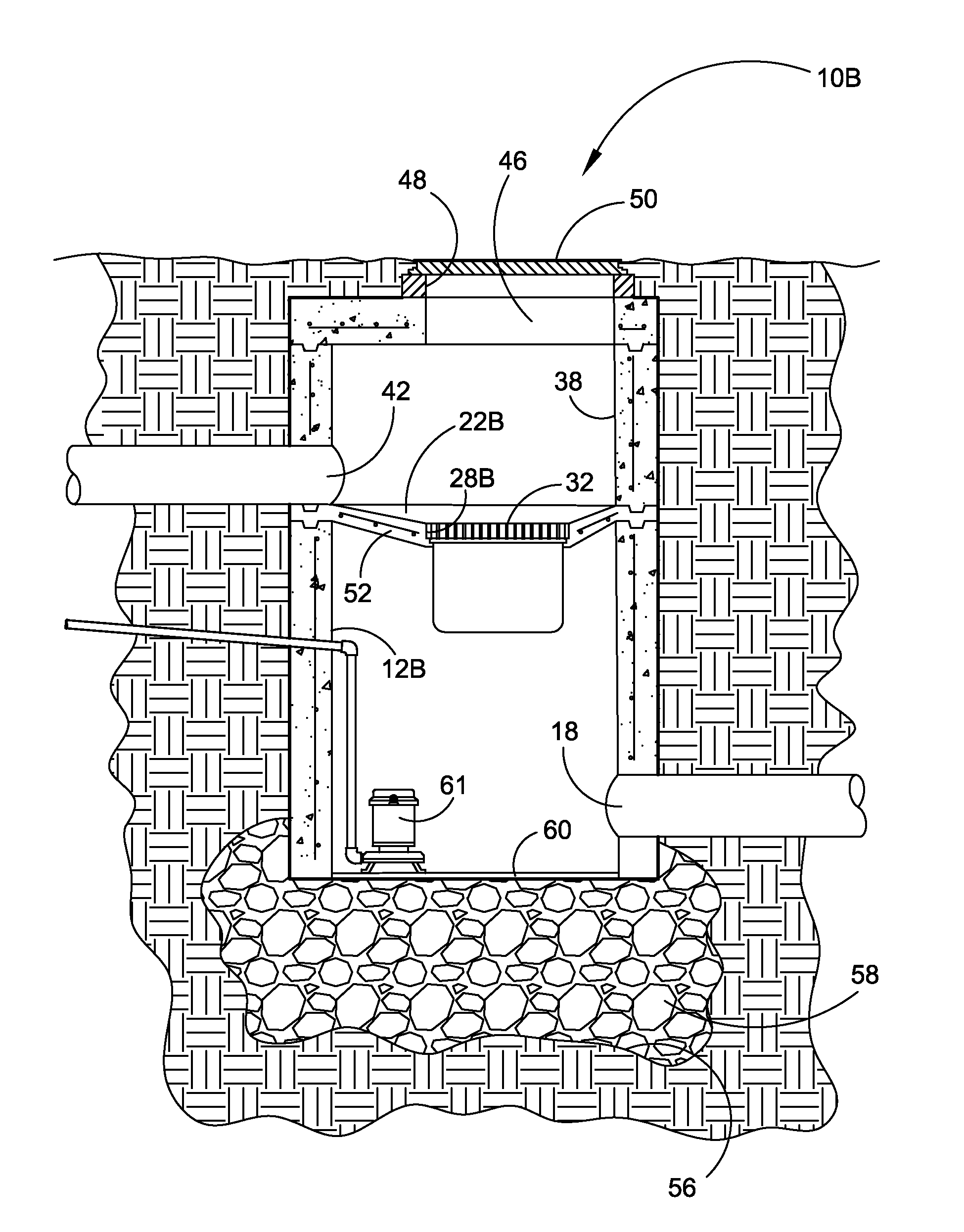
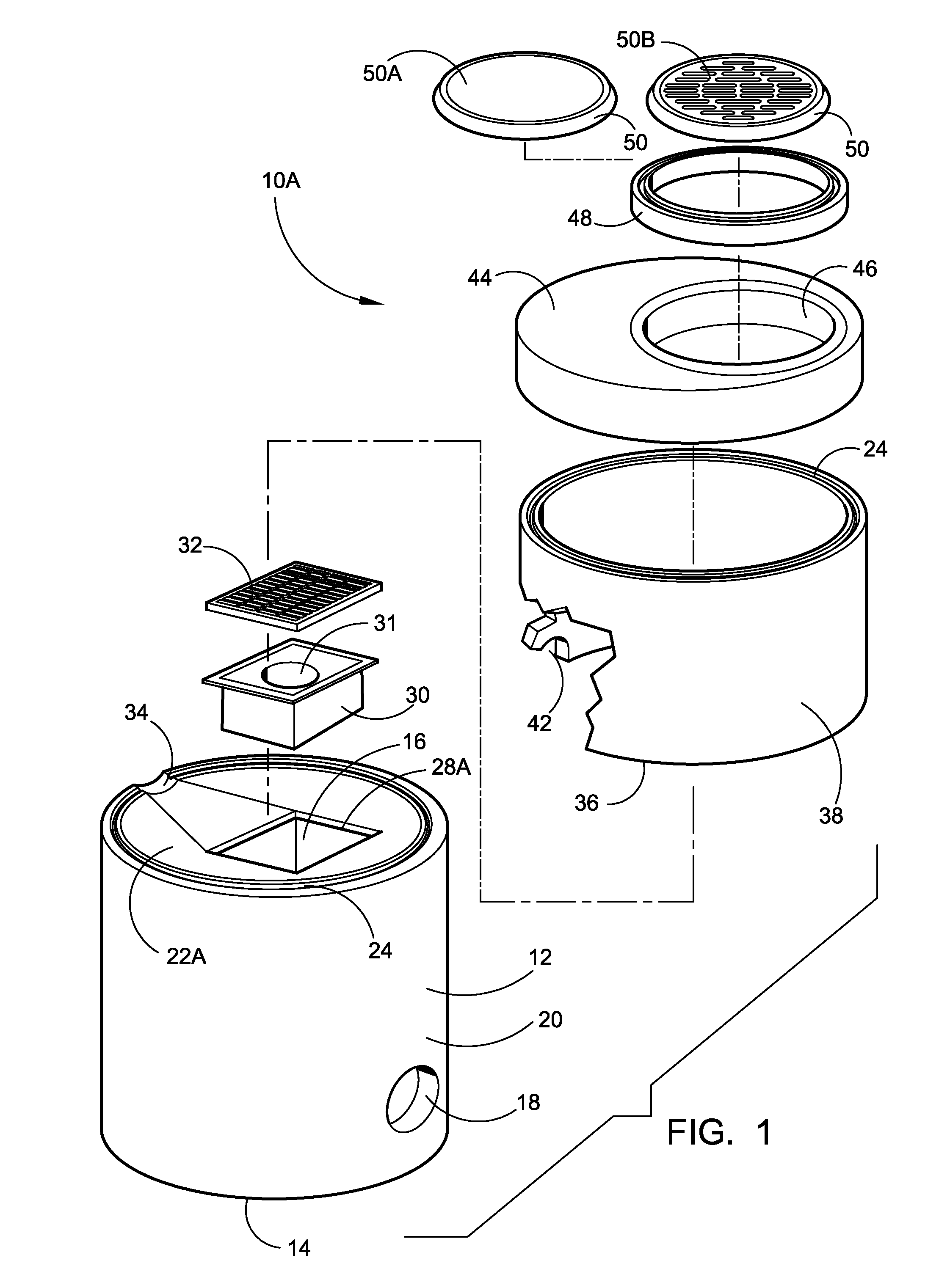
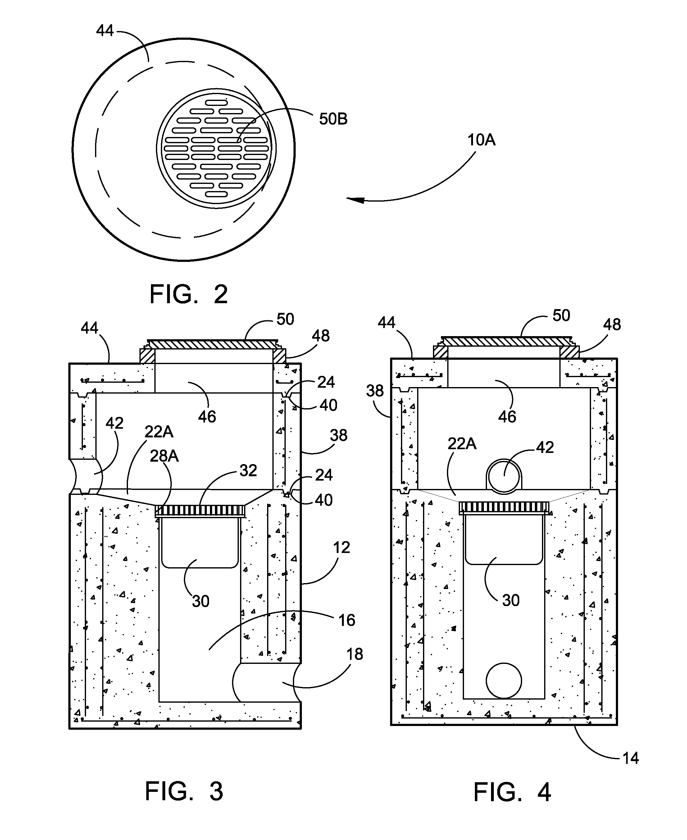
[0037]Referring now to the drawings, wherein similar parts of the invention are identified by like reference numerals, there is seen in FIG. 1 a perspective exploded view of the integrated belowground vault with filter catch basin 10A. The device consists of a one piece lower vault section or housing 12A that is preferably cylindrical in shape with a solid concrete bottom 14, although other shapes and configurations may be used. As shown, the center of the lower vault has a cuboid interior cavity 16 that is offset from the diametric center of the cylinder. At the bottom of the interior space, there is a cylindrical outlet orifice 18 in the wall 20 of the lower vault section 12A. The top surface 22A of the lower vault section 12A has an interlocking female groove 24 around the outside edge with the central area sloping towards the center of the cuboid interior cavity 16. A recess 28A at the top of the cuboid interior cavity 16 permits the insertion of the removable filter unit 30 hel...


PUM

PropertyMeasurementUnit
sizesaaaaaaaaaa
depthaaaaaaaaaa
timeaaaaaaaaaa

Abstract

The invention relates to an integrated belowground vault with filter catch basin, that allows the runoff water to enter into a belowground two-part vault passing through a commercially available replaceable filter before being transferred out to the sewer, Rood control system or out through a French drain consisting of a cavity below the device that is filled with drain gravel. A layer of filter cloth can optionally be placed over the drain gravel. This device will be manufactured in variety of sizes and shapes and made from several different materials. The device has the unique ability of being capable of filtering low flow water runoff while allowing high volume to pass through with the added benefit of not retaining water that can become a mosquito breeding ground.

Description

[0001]The present invention is a continuation-in-part of U.S. patent application Ser. No. 11 / 046,490, filed on Jan. 28, 2005, now U.S. Pat. No. 7,163,635 and herein incorporated by reference in its entirety.FIELD OF THE INVENTION[0002]The present invention relates to an improvement in the field of handling, purification and dispersement of residual and commercial run-off water and more particularly, but not by way of limitation, to a novel method of the removal of water-borne pollutants such as vegetation, litter, coarse sediments, petroleum hydrocarbons and other pollutants and contaminants from residential and commercial run-off water. More specifically, this invention supplies a belowground vault composed of several parts and in a variety of sizes and shapes with a replaceable basin insert filter for this purpose.BACKGROUND OF THE INVENTION[0003]The inventor, while working in the plumbing field has found the need for the purification of run-off water from residential and commerci...

Claims


Application Information

Patent Timeline
Patent Type & Authority Patents(United States)
IPC IPC(8): E03F5/14
CPCE03F1/00E03F5/0404C02F1/004C02F2103/001E03F5/14
Inventor FITZGERALD, JAMES
Owner FITZGERALD JAMES
Why Eureka
Try Eureka