Electronic display panel

a display panel and display panel technology, applied in the direction of static indicating devices, instruments, cathode-ray tube indicators, etc., can solve the problems of continuous display, large and expansive panels are often cumbersome and difficult to handle, and the changeout of components is difficult, so as to achieve easy and convenient installation, easy and convenient secure, and simple engagement

Inactive Publication Date: 2009-10-20
DAKTRONICS
View PDF10 Cites 60 Cited by
  • Summary
  • Abstract
  • Description
  • Claims
  • Application Information

AI Technical Summary

Benefits of technology

[0007]According to one embodiment of the present invention, there is provided an electronic display panel having a combination of aligned and connected forwardly located components and a plurality of rearwardly located LED (light emitting diode) modules easily and readily secured to the combination of aligned and connected forwardly located components. The major forwardly located components include in order from front to back a front panel, a polycarbonate panel, a seal, spacer brackets, and a rear panel and rearwardly located LED (light emitting diode) modules. The rearwardly located LED modules include an insertion panel having offset tabs and an opposed latch which readily engage the rear panel of the forwardly located components in three-point attachment. The geometry of the forwardly located components and the rearwardly located components is configured together or separately to offer minimum dimension structure where panels or edges of panels are mated and / or joined. Such dimension minimalizing allows uniform spacing of the LED pixels across each of the adjacent LED modules, as well as across adjoining forwardly located components. The spacer brackets are configured in a manner to offer mutual spaced support between the front and rear forwardly located panels and also are constructed for dimension minimalizing such that they will not interfere with the viewing of the LEDs. Notches are located along the bottom edge of the electronic display panel for simple engagement, such as with an arcuate surface of a pivot bar incorporated in the lower structure of a sign system. The geometry of the upper region of the electronic display panel is suitable for accommodation by and for securing to the upper structure of a sign system.
[0008]One significant aspect and feature of the present invention is an electronic display panel which can be easily and readily accommodated by and attached using minimal personnel to the frontal geometry of an electronic sign system.
[0011]Still another significant aspect and feature of the present invention is an electronic display panel having spacer brackets having recesses and which are joined as an assembly to maximize strength along and about the general structure while still allowing maximum viewing of LED pixels.
[0012]Yet another significant aspect and feature of the present invention is an electronic display panel having a rear panel featuring square viewing openings for the purpose of weight reduction and for providing access to the interior of the electronic display panel for cleaning of the interior of the electronic display panel.
[0013]A further significant aspect and feature of the present invention is the use of LED modules which simply and readily attach or detach from a rear panel.

Problems solved by technology

Such large and expansive panels are often cumbersome and difficult to handle because of physical size and weight.
Also, they often present problems associated with changeout of components.
Other problems relate to maintaining a flat and planar well supported frontal viewing area over such an expansive viewing site.
In the event that prior art electronic displays incorporated multiple panels across a large viewing area, the juxtaposing of individual display panels presented the problem of maintaining a continuous display without having undesirable spacing between the visually sensed LED pixels.

Method used


Image

  • Electronic display panel
  • Electronic display panel
  • Electronic display panel

Examples


Embodiment Construction

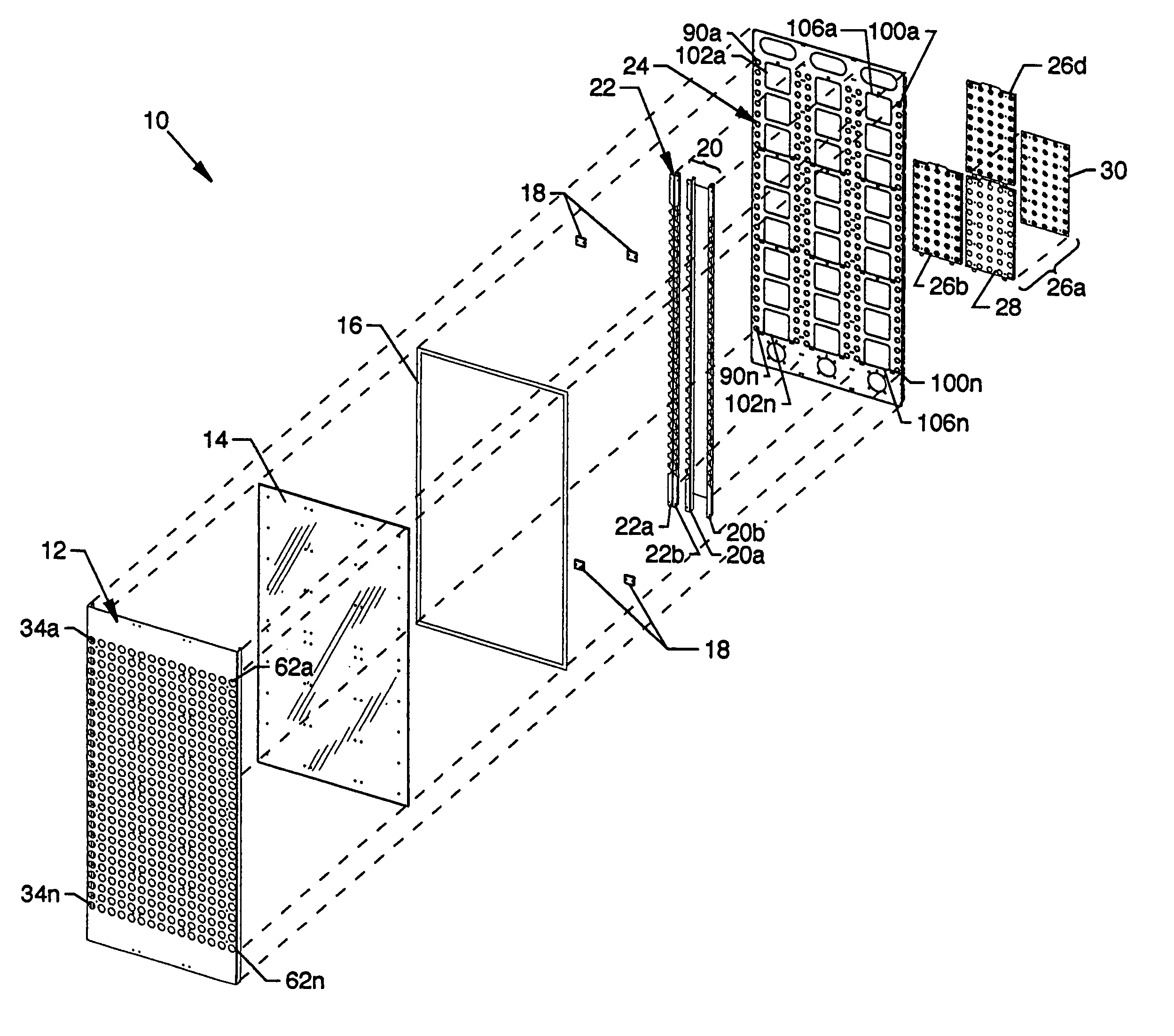
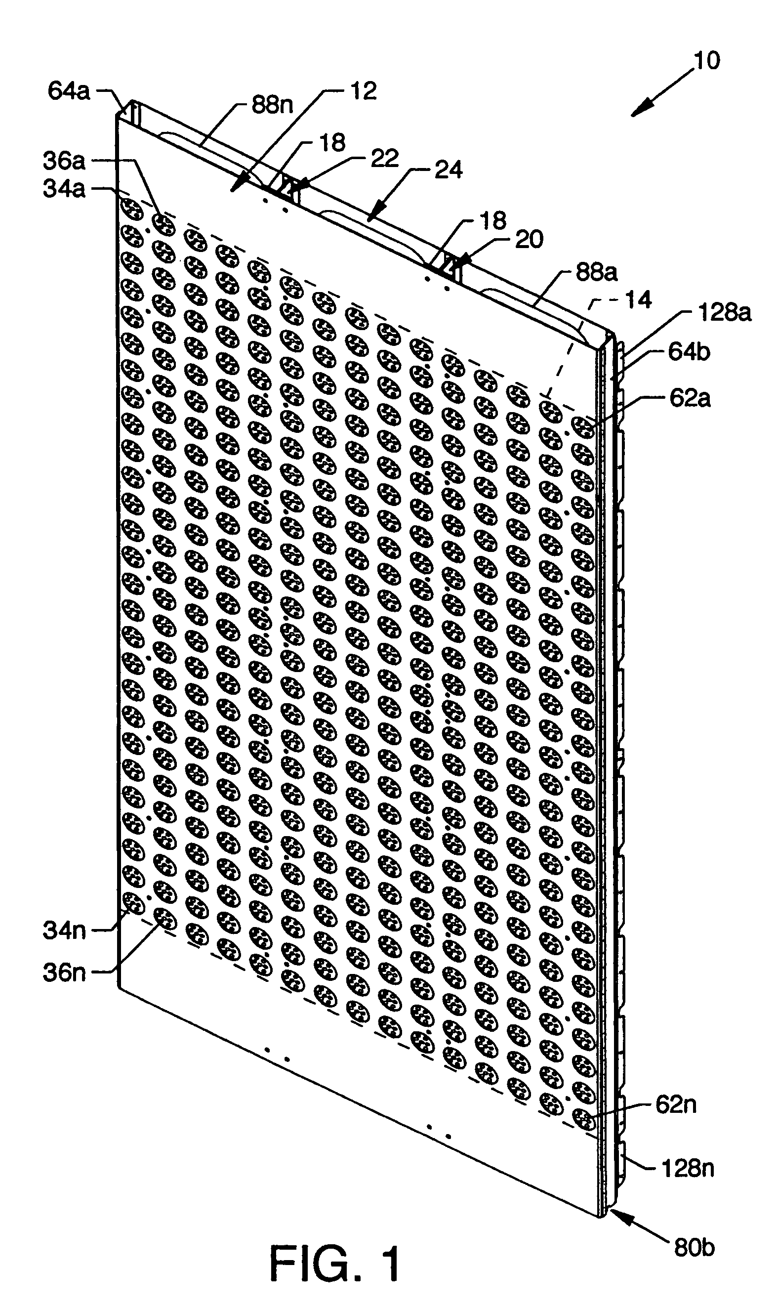
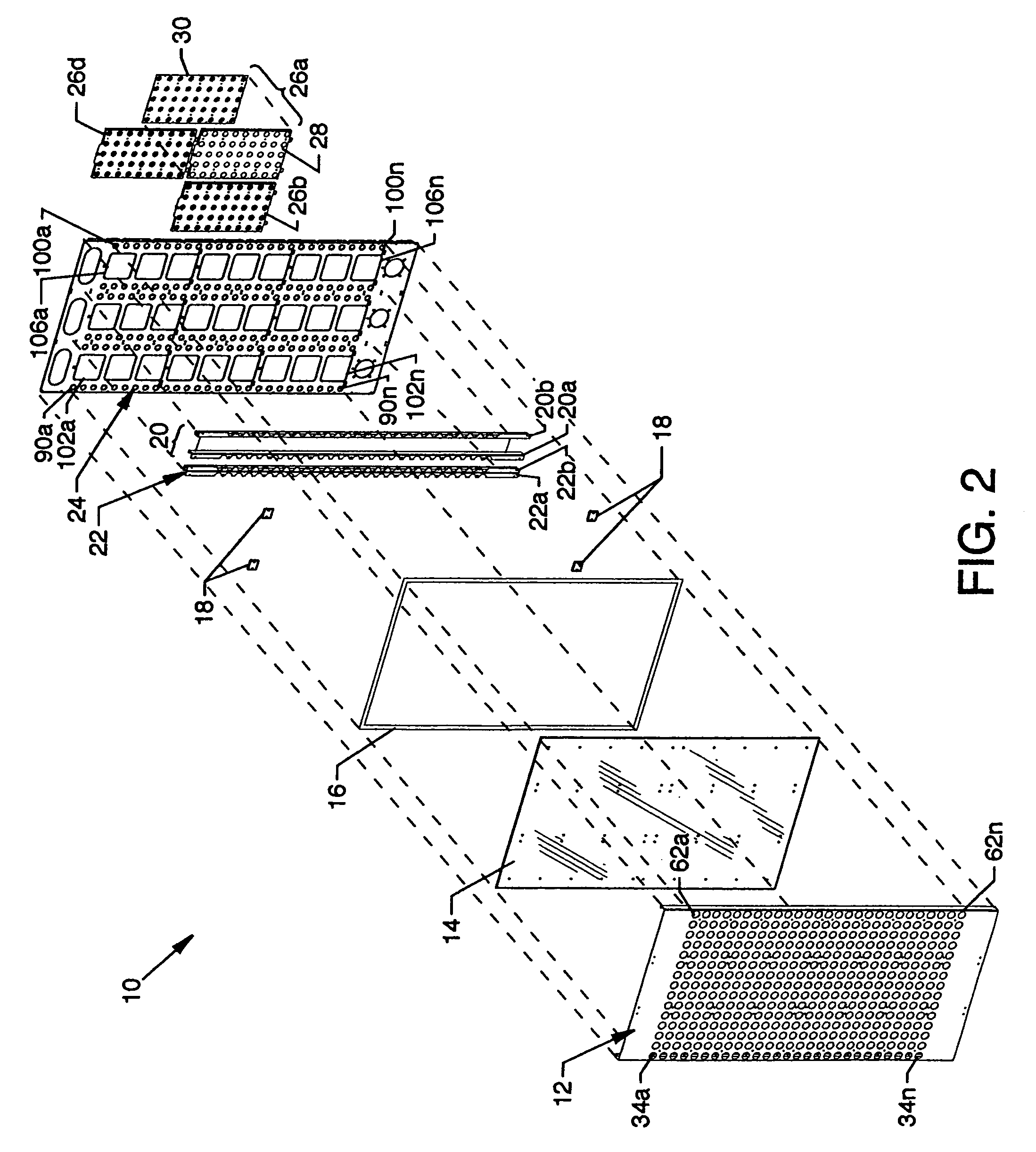
[0034]FIG. 1 is a an isometric front view of an electronic display panel 10, the present invention; FIG. 2 is an exploded isometric front view of the electronic display panel 10; and FIG. 3 is an exploded isometric rear view of the electronic display panel 10. With reference to the aforementioned figures, the electronic display panel 10 includes, from front to back, a front panel 12, a polycarbonate panel 14, a seal 16, a plurality of small spacers 18, vertically oriented spacer bracket assemblies 20 and 22 formed of suitably joined spacer brackets 20a and 20b and spacer brackets 22a and 22b, respectively, a rear panel 24, and a plurality of LED modules 26a-26n of which a small number are shown in FIG. 2. The LED module 26a is shown in exploded view to reveal an insertion panel 28 and an LED display panel 30.

[0035]FIG. 4 is an isometric rear view of the front panel 12 including an apertured planar section 32 with a plurality of spaced circular openings 34a-34n . . . 62a-62n arranged...


PUM


Abstract

An electronic display panel having a combination of aligned and connected forwardly located panels to which a plurality of rearwardly located LED modules easily and readily secure using three-point attachment to form an electronic display panel suitable for accommodation by and for securing to the structure and framework of a sign system. Configured spacer brackets offer mutual spaced support between the front and rear panels and are constructed using arcuate geometry for dimension minimalizing to prevent interference with the viewing of the LED pixels. Notches are located along the bottom edge of the electronic display panel for simple engagement, such as with an arcuate surface of a pivot bar incorporated in a lower structure of a sign system.

Description

CROSS REFERENCES TO RELATED APPLICATIONS[0001]This patent application is a continuation-in-part of application Ser. No. 11 / 148,461 entitled “Sign System” filed on Jun. 09, 2005, which is pending.BACKGROUND OF THE INVENTION[0002]1. Field of the Invention[0003]The present invention is for an electronic display panel, and more particularly, pertains to a modularized electronic display panel easily and readily installed for use in a sign system.[0004]2. Description of the Prior Art[0005]Prior art electronic display panels have often been large expansive displays utilizing a continuous collection of front, mid and rear panels to achieve the wide breadths thereof. Such large and expansive panels are often cumbersome and difficult to handle because of physical size and weight. Also, they often present problems associated with changeout of components. In particular, if multiple LED panels and support structure were incorporated, a plurality of fastening hardware pieces had to be removed bef...

Claims


Application Information

Patent Timeline
Patent Type & Authority Patents(United States)
IPC IPC(8): G09G5/00
CPCG09F9/3026G09F9/33
Inventor SYRSTAD, JOHN W.
Owner DAKTRONICS
Why Eureka
Try Eureka