Combined ladder engageable tool carrier and step stool

a tool carrier and step stool technology, applied in the field of multi-functional tool carriers, can solve the problems of affecting the user's work, and affecting the user's work, and achieve the effect of simple non-attachment engagemen

Inactive Publication Date: 2013-02-21
PADILLA RICHARD
View PDF14 Cites 4 Cited by
  • Summary
  • Abstract
  • Description
  • Claims
  • Application Information

AI Technical Summary

Benefits of technology

[0018]In a first preferred as used mode, which provides the user a stationary positioning for tools and the like at an elevated job height, the device is adapted for a simple non-attachment engagement over the top platform of a conventional folding step ladder. In this first mode, engaged upon the top platform and held in place by gravity and a skirt surrounding the platform, the device provides a hand accessible container for tools to be used, thus eliminating the need for a user to employ a tool belt when working atop the ladder. Since a number of tools may be held by the device engaged

Problems solved by technology

The tool belt is often the most desired choice of carrying means by workers since it allows them to maintain most, if not all, needed tools close by and at all times. However, if a user has many tools, the belt can become heavy and undesirably bulky, and possibly interfere with the job at hand.
As such, the tool belt which is a device that was meant to help with the job is merely interfering and slowing down the user.
Further, although a tool box will similarly become quite bulky and heavy given a plurality of tools, a user will typically place the tool box in one location on a work site and simply return to the box as needed to acquire the correct tool.
However, while constant retrieving relieves the problem of carrying a plurality of heavy tools on their person, the task of continuously returning to the tool box wastes time, especially if an incorrect tool was chosen accidentally, or if the job at hand requires the user to change tools frequently.
Further, the conventional tool box is limited to the formed compartments within the interior and is not easily modified to accommodate all types of tools.
As outlined above, conventional tool carrying devices fall short in providing convenient and effective tool carrying methods.
These devices further inconvenience should user visits be required if positioning for the task at hand is more involved.
Ladders are known to vary greatly in size and height and wh

Method used


Image

  • Combined ladder engageable tool carrier and step stool
  • Combined ladder engageable tool carrier and step stool
  • Combined ladder engageable tool carrier and step stool

Examples


Embodiment Construction

[0054]In this description, the directional prepositions of up, upwardly, down, downwardly, front, back, top, upper, bottom, lower, left, right and other such terms refer to the device as it is oriented and appears in the drawings and are used for convenience only; they are not intended to be limiting or to imply that the device has to be used or positioned in any particular orientation.

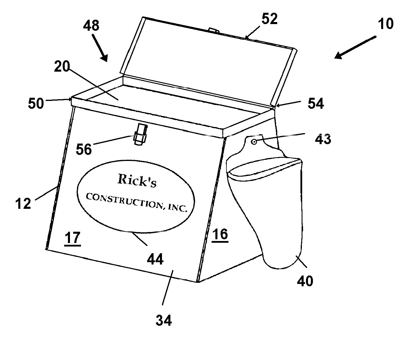
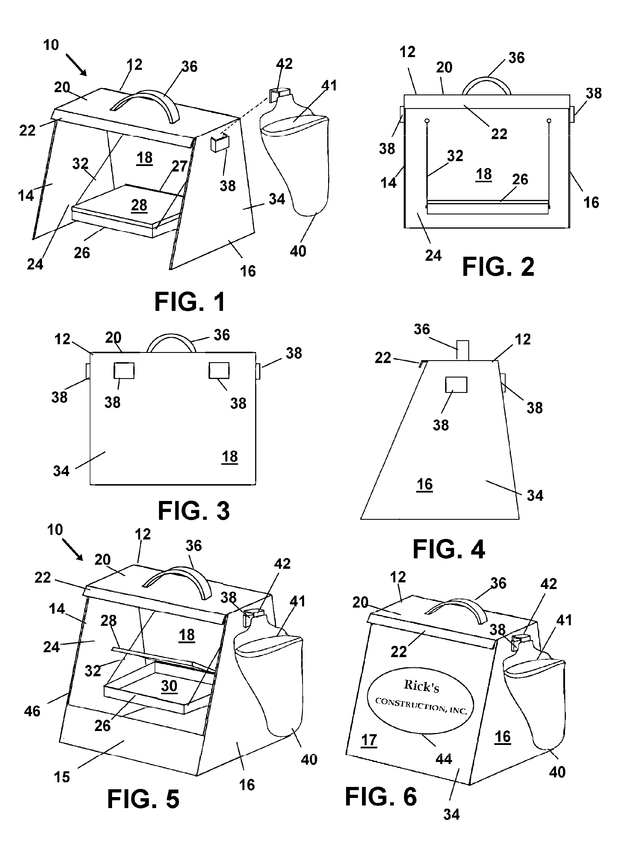
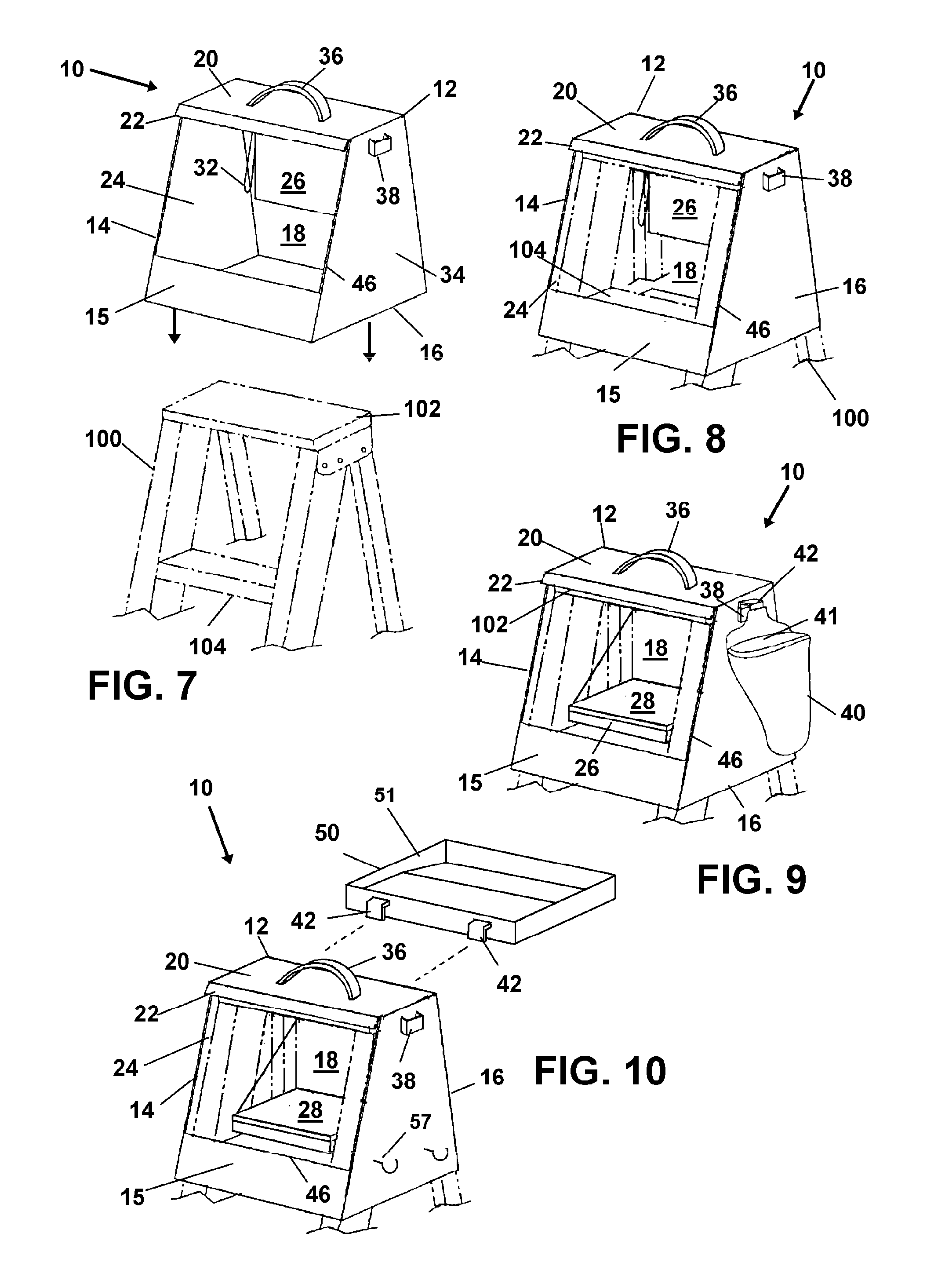
[0055]Now then, referring to drawings in FIGS. 1-12, wherein similar components are identified by like reference numerals, there is seen in FIG. 1 an perspective view of a preferred mode of the device 10 which is employable as a step stool. As shown in FIG. 1, the device 10 in this mode when employed as a step stool, is placed on ground or other support surface where a step stool is desired. The sidewalls provide a rigid structure for the top wall 20 which provides a platform for supporting a users weight in an elevated position. In this mode, the device 10 is generally formed of a rigid durable sheet...


PUM


Abstract

A tool carrying device configured for removable engagement atop a stepladder and to provide elevated support for a user when the carrying device is positioned on the ground. A secure removable engagement with the top of the ladder is provided by walls descending from a top which form a skirt to surround the top end of the ladder and hold the device from sliding therefrom. Removable tool holders and shelves to hold and store tools are provided, allowing the user a secure tool box when atop a ladder and a slightly elevated working structure for tasks requiring a lower elevation for the user.

Description

BACKGROUND OF THE INVENTION[0001]1. Field of the Invention[0002]This application claims priority to U.S. Provisional Application Ser. No. Number 61 / 524,700 filed on Aug. 17, 2011 and incorporated in its entirety by reference thereto.[0003]The present invention relates generally to tool containers and holders. More particularly, the disclosed device relates to a multi-function tool carrier providing, in one preferred as-used engaged mode, a ladder-engageable tool holder / container, and in a second preferred mode, a combined step stool and tool holder / container.[0004]2. Prior Art[0005]Service and maintenance industries including construction, demolition, plumbing, electrical, landscaping, janitorial, and the like conventionally require workers to use and thus carry many hand tools and other equipment through their workday. Conventional methods for the transport, carry, and organization of tools include tool boxes, belts, buckets, bags, packs and various others containers.[0006]The typi...

Claims


Application Information

Patent Timeline
IPC IPC(8): E06C7/14
CPCE06C7/14
Inventor PADILLA, RICHARD
Owner PADILLA RICHARD
Why Eureka
Try Eureka