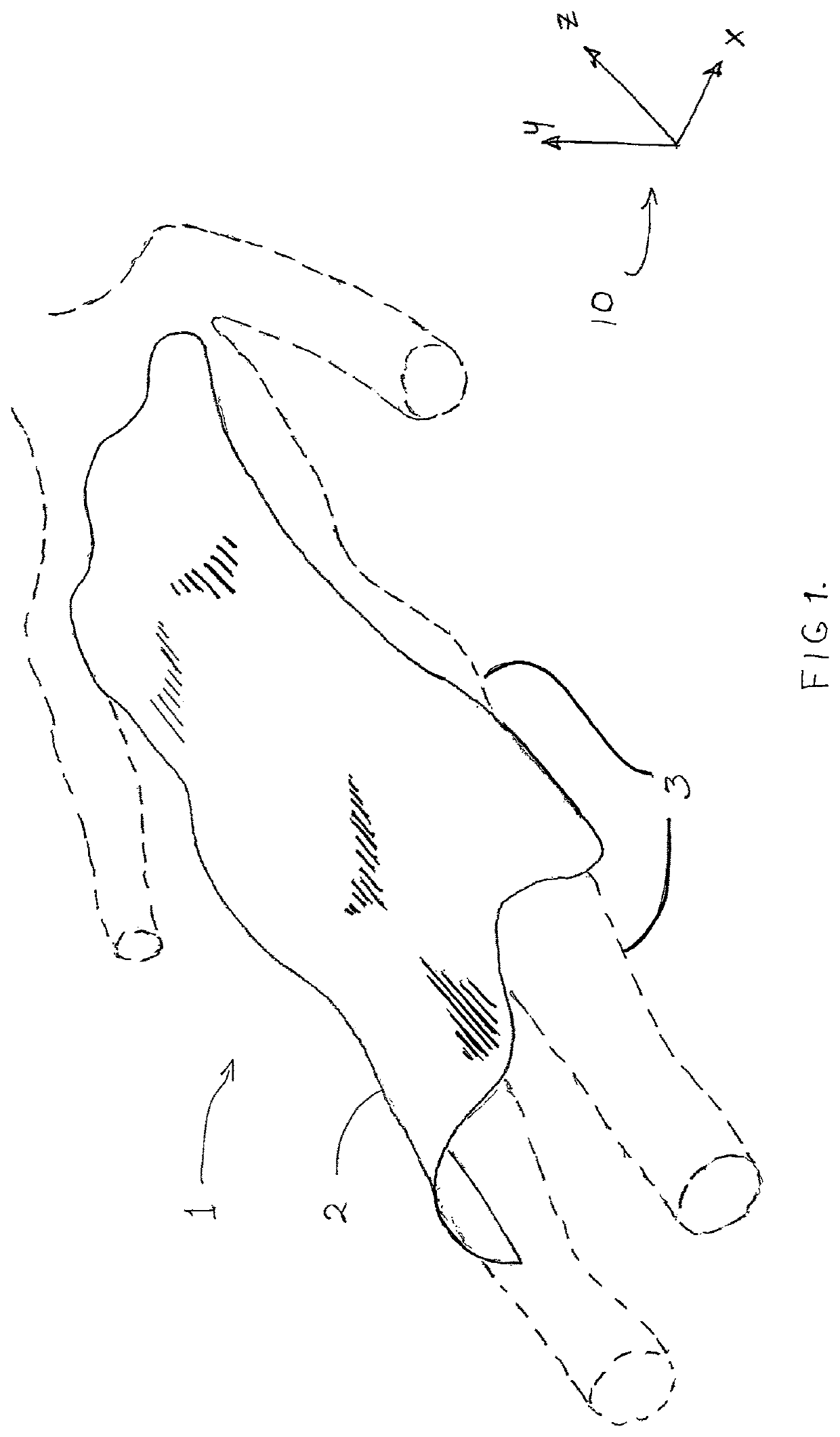
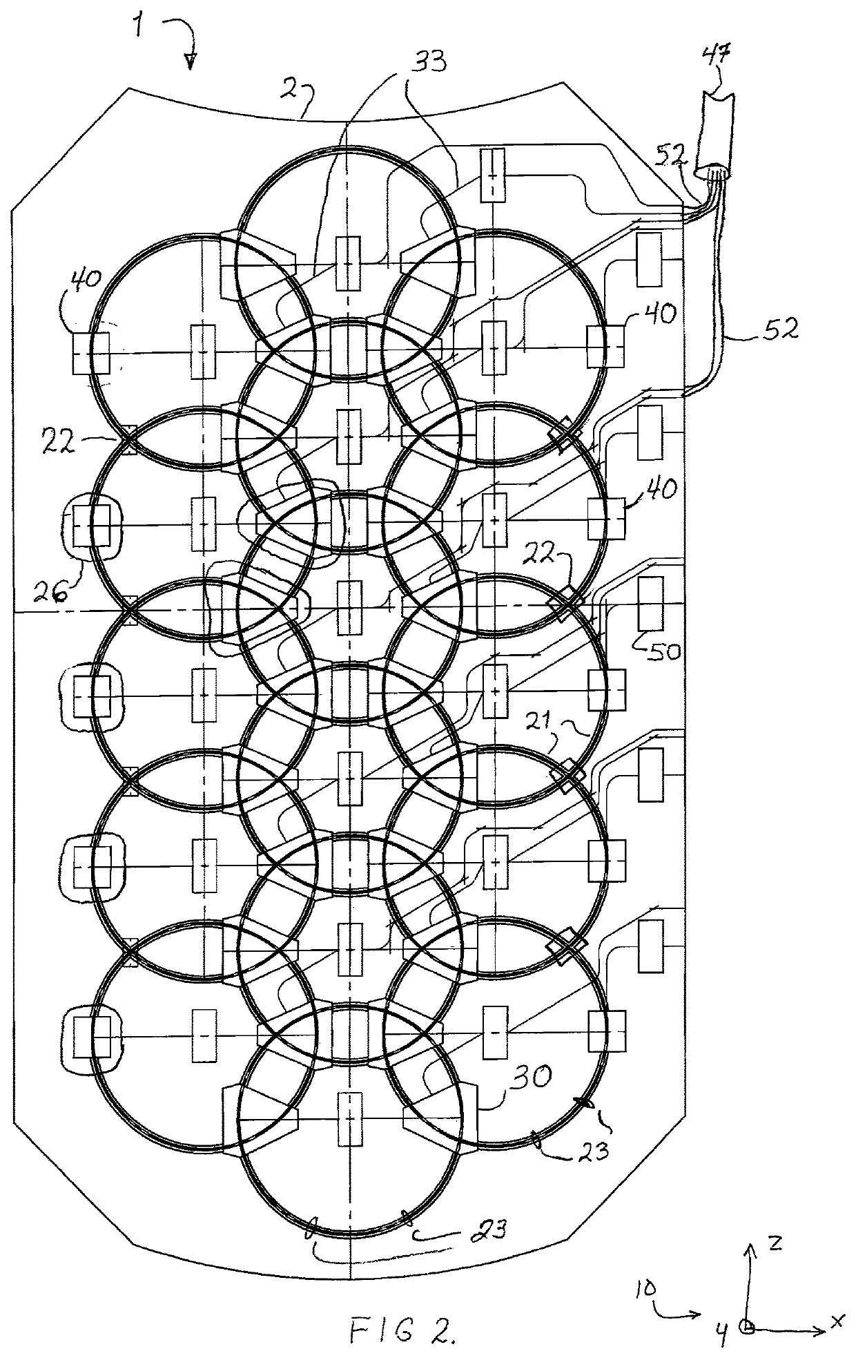
[0032]The present invention is directed toward an MRI antenna array including a flexible housing, and a flexible substrate, flexible antenna elements and circuitry encapsulated by the housing. The housing is sufficiently flexible to allow it to be draped over or wrapped about a portion of a patient and distort in three dimensions to closely conform to contours of the patient. The antenna elements are attached to the substrate in a manner that permits each element to maintain a desired resonance when the housing is distorted in three dimensions. The circuitry is attached to the substrate and electrically coupled with the antenna elements for maintaining tuning and isolation between the elements when the housing is distorted in three dimensions. The array may be formed as a blanket that may be draped over a patient.
[0033]The present invention is also directed toward an MRI antenna array including a flexible and elastic housing, and a flexible and elastic substrate, flexible and elastic antenna elements and circuitry encapsulated by the housing. The housing is sufficiently flexible and elastic to allow it to be worn by a plurality of different sized patients so that the housing is in close contact with the patient and conforms to contours of the patient. The antenna elements are attached to the substrate in a manner that permits each element to maintain a desired resonance when the housing is distorted in three dimensions. The circuitry is attached to the substrate and electrically coupled with the antenna elements for maintaining tuning and isolation between the elements when the housing is distorted in three dimensions. The array may be configured to be worn over any portion of a patient's body, including the pelvis, shoulder, and the entire body.
[0034]In another embodiment, the invention is directed toward an MRI antenna array including a flexible housing and a flexible substrate, plurality of antenna elements, and circuitry that are encapsulated by the housing. The housing is lightweight, load bearing, compressible, and insulative and includes a surface for covering a designated portion of a patient. The housing is cut or pressed into a set of connected geometrical shapes positioned between the cut or pressed areas, which allows for smaller bend radii than a non-cut or pressed thick layer. The antenna elements and circuitry are mounted to the substrate, and the circuitry is electrically coupled with the antenna elements.
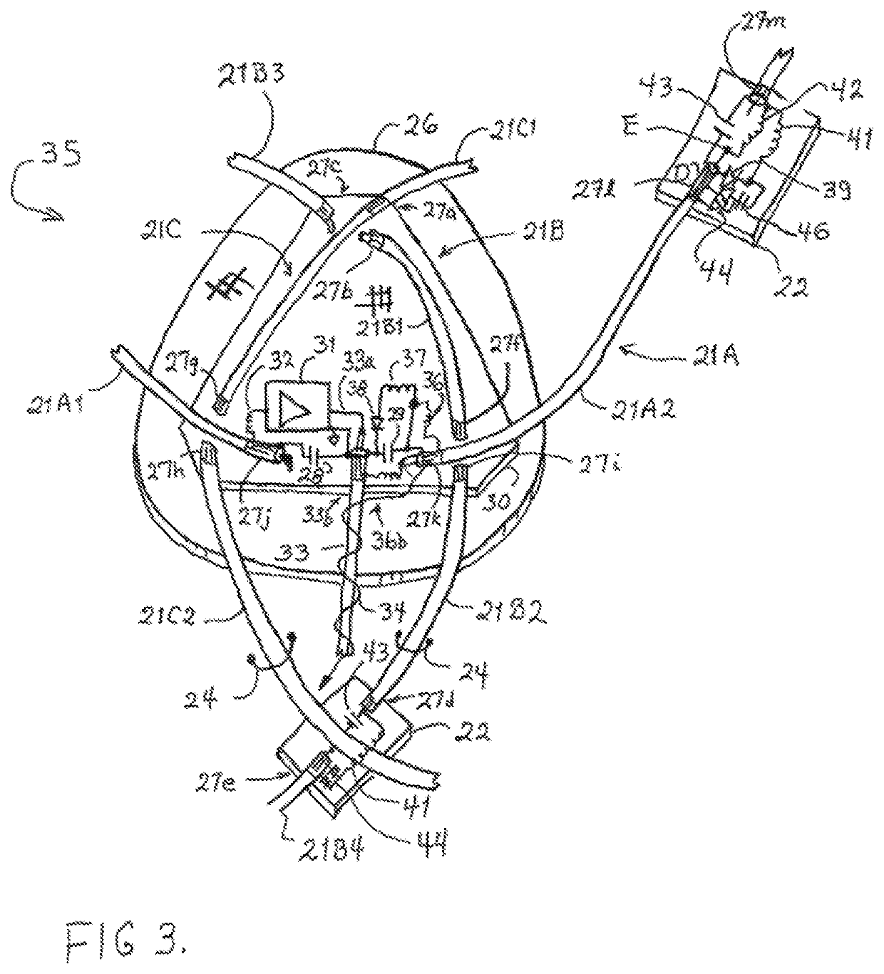
[0035]The present invention is an MRI antenna array constructed in such a way so as to be highly flexible and drape, fit, or conform to a myriad of different shapes and sizes associated with the human anatomy—all while offering optimal S / N ratio from the anatomy in question. Preferably, the invention includes the design of high Q resonating elements from highly flexible conductors whereby they are attached to a flexible, thin, durable substrate which, in combination with element sizing, spacing, and location, keeps them in relative position to one another and maintains isolation amongst the many elements. In addition, one embodiment is to employ elements that are constructed from a conductor which has the properties of expansion / contraction to accommodate stretching with the substrate material to which they are affixed. The attachment points serve also as circuit mounting locations for tuning, matching and isolation components as well as miniature isolation preamplifiers mounted directly in each element's radio frequency current pathway; thus significantly reducing coupling mechanisms and stray loop currents associated with larger circuit boards and component spacing. Preferably, the elements, their isolation and amplification circuitry, and output cabling are embedded in a lightweight, durable, water resistant, biocompatible, cleanable, highly flexible, foam housing. Preferably, the foam housing is thick and compressible enough to be comfortable for the patient to lie upon, yet exhibit a high degree of flexibility along three axes so as to conform to wide ranges of anatomical variations. This accommodation to fitting a range of anatomical sizes ensures that the coil elements are positioned as closely as possible to the target tissues; hence, optimizing the signal derived from the target anatomy based upon minimizing the distance from the target to the antenna elements.
[0036]In one embodiment of the invention, stiffeners are added within the encapsulating foam so as to restrict the bending in certain situations whereby the desire is for the flexible array to be self-supporting within a certain region.
[0039]The present invention preferably optimizes coil size, configuration, the number of coil elements or resonators, and the positioning of those resonators about the subject via their being mounted on a flexible substrate, in order to achieve the desired performance, both in terms of S / N ratio, coverage and homogeneity. Further, the resonators are isolated from one another to such a degree so as not to interfere with one another's tuning and performance, and are preferably housed in a water-proof container that facilitates close fitting to the desired patient anatomy via draping the coil over, around or embedding the array within a pull-on garment. Further, these arrays will withstand high degrees of flexing in three dimensions and also withstand the weight of the patient distributed over the surface of the coil housing. Isolation amongst elements is achieved via a combination of two or more mechanisms: 1) geometric isolation between two elements sharing a common sensitivity volume—meaning that their exists little to no inductive coupling between the elements due to their net orthogonal vector sensitivity profiles within the common volume; 2) inductive isolation by means of overlapping elements such that adjacent coil elements have net mutual inductance; 3) reactive isolation by means of a given capacitance or inductance connecting two nearby elements such as to cancel any mutual inductance between the two elements; 4) transformer isolation between two nearby elements whereby currents from each element flow through separate windings of a dual winding transformer in opposite directions and with the proper transformer coupling coefficient to cancel the mutual inductance of the two elements; and 5) the use of low impedance amplifiers and matched input isolation reactances that create a high impedance “trap” to the mutually induced currents from one element to another.