
Umbilical cord cell harvesting

a technology of umbilical cord and cell, which is applied in the field of umbilical cord cell harvesting, can solve the problems of reducing the service life of the patient, reducing the safety of the patient, so as to reduce the diameter of the sleeve and facilitate the movement of the actuator. , the effect of preventing backlash

Inactive Publication Date: 2012-12-11
KUZYK ROMAN
View PDF2 Cites 0 Cited by
  • Summary
  • Abstract
  • Description
  • Claims
  • Application Information

AI Technical Summary

Benefits of technology

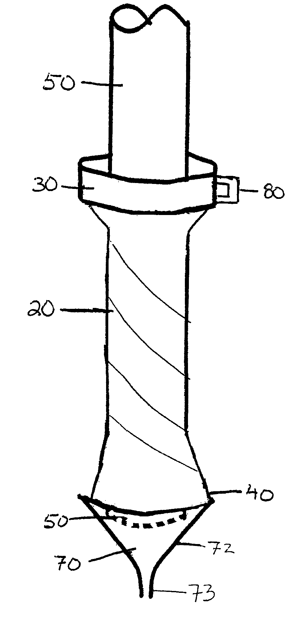
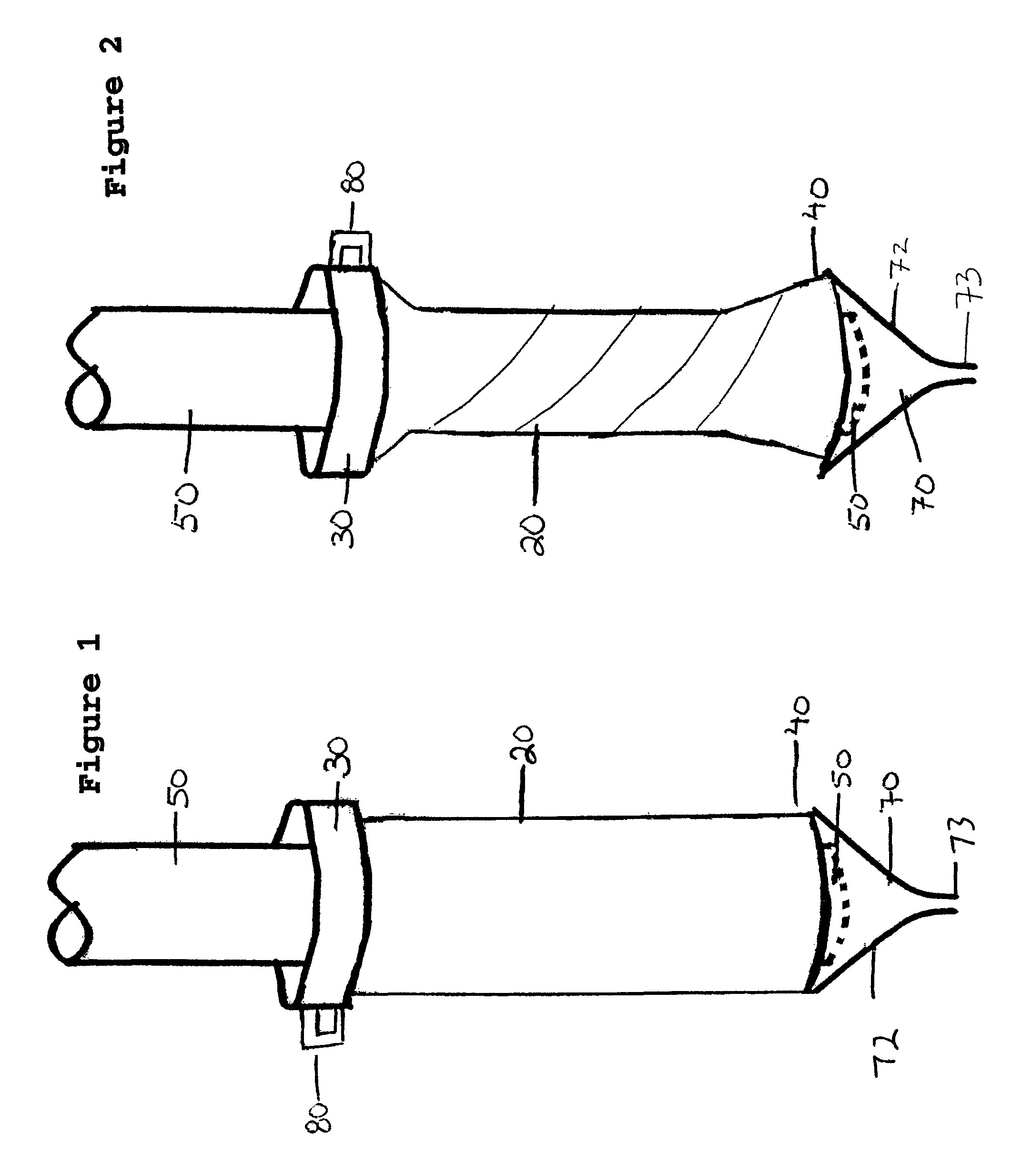
[0008]In one embodiment, a seal member may be provided to seal an open end of an umbilical cord relative to a collection drain. The seal member may be sealably engageable with an umbilical cord and sealable or sealed relative to the drain to facilitate drainage of desired material from the umbilical cord and to prevent leakage. The seal member may be in the form of a sealing sleeve which may preferably be adjustable or movable into sealing engagement with an exterior surface of an umbilical cord. Optionally, the sealing sleeve may be stretchable in an axial direction and twistable and stretchable in a rotational direction. The sleeve may be sufficiently elastic so as to return to or approximately to its original shape after stretching or deformation. The seal member functions to seal an open end of an umbilical cord with a drain to effect drainage of fluid extracted from the cord. A support may be provided for supporting the seal member in a desired position or orientation. An actuator may be provided to actuate or facilitate actuation or adjustment of the seal member into a sealing relationship with the cord so fluid may drain from the cord without leakage or optimally without exposure to atmosphere. Movement of the actuator relative to the support may function to cause sealed engagement of the seal member with the cord. The seal member may be bonded or otherwise sealed relative to the drain to prevent leakage of material from the apparatus. Sealed engagement of the seal member with the cord prevents overflow of material flowing from the umbilical cord toward the drain.
[0010]The actuator cooperates with the seal member in order to move or twist the seal member in a desired manner. In this regard, moving the actuator relative to the support tube functions to move the seal member within the support tube so as to sealably engage relative to the umbilical cord. By moving the seal member into sealed engagement with the outer surface of the umbilical cord, the seal member may be used with cords of varying diameter. More specifically, for example, the actuator may rest on top of or be supported in position at the top of the support tube with the actuator cogs at a bottom of the actuator in engagement with the support cogs at the top of the support tube. As the actuator is twisted or turned relative to the support, a ring of actuator cogs rides on a ring of support cogs to permit rotational movement of the actuator relative to the support tube which in turn causes the seal member to adjustably engage or twist about an umbilical cord. The cogs may be configured to prevent backward rotational movement of the actuator relative to the support tube to prevent backlash by the twisting seal member.
[0011]In another embodiment, the seal member may include a moveable or twistable sealing sleeve such as an elastic tubing. The tubing may be dimensioned to enclose and engage at least a portion of a fluid-filled tube, such as an umbilical cord, when the cord is positioned within the sleeve. Specifically, an umbilical cord may be positioned within the elastic sleeve. The sealing sleeve may include a cord-engaging portion and a base portion. The cord-engaging portion permits the insertion of the umbilical cord or other fluid-filled tube and functions as a cord-sealing portion to seal to an exterior surface of the inserted umbilical cord. The base portion functions as a drain-sealing portion to seal relative to the drain so that the sealing sleeve functions to seal the open end of an umbilical cord relative to the drain. The sleeve may be twisted or moved starting from the cord-engaging portion towards the base portion to lightly engage the umbilical cord or fluid-filled tube. As the sealing sleeve is twisted about the cord, the sealing sleeve sealably engages the exterior of the cord and thereby seals the open end of the umbilical cord relative to the drain. A base or support may be provided to support the sleeve in a desired position, for example, to receive the open end of an umbilical cord to permit drainage of fluid from such open end. The actuator communicates with the sleeve so that movement of the actuator causes movement of the sleeve so as to decrease the diameter of the sleeve until the sleeve sealably engages an outer circumferential surface of the umbilical cord. The actuator may include a handle that enables easier movement of the actuator. The actuator may be positioned or supported relative to the base so that movement of the actuator enables the sleeve or elastic tubing to surround and engage the umbilical cord to seal the seal member with the umbilical cord to facilitate drainage of fluids from the umbilical cord towards a drain. Specifically, as material flows from the cord through the drain, sealable engagement of the seal member with the cord and relative to the drain prevents overflow of material out of the apparatus.

Problems solved by technology

The use of needles has the limitation that a conventional needle has a relatively small diameter relative to the diameter of the cord.
Another drawback of the traditional methods used to collect material from umbilical cords is that the use of needles and syringes present potentially dangerous situations for medical personnel.
Whenever a needle is used for a medical procedure, a risk exists that the personnel may be inadvertently stuck by the needle and contract disease or blood-borne illness.
As such, using needles to collect biological material from umbilical cords may be inefficient and may also create a potential hazard for medical personnel.

Method used


Image

  • Umbilical cord cell harvesting
  • Umbilical cord cell harvesting
  • Umbilical cord cell harvesting

Examples


Embodiment Construction

[0020]Referring now to the Figures in general, wherein like reference numbers refer to the same components across the several views, there is shown an apparatus, generally designated 10, for harvesting biological material from an umbilical cord. In general application, the apparatus 10 may be used to drain biological material from a fluid-filled tube such as a vein, vessel, cord member or other tubular member. In specific application, the apparatus 10 may be used to drain biological material, including fluid, blood, cells, and specifically stem cells, from an umbilical cord. Preferably, the apparatus 10 may be used to drain biological material from across the entire diameter of the umbilical cord.

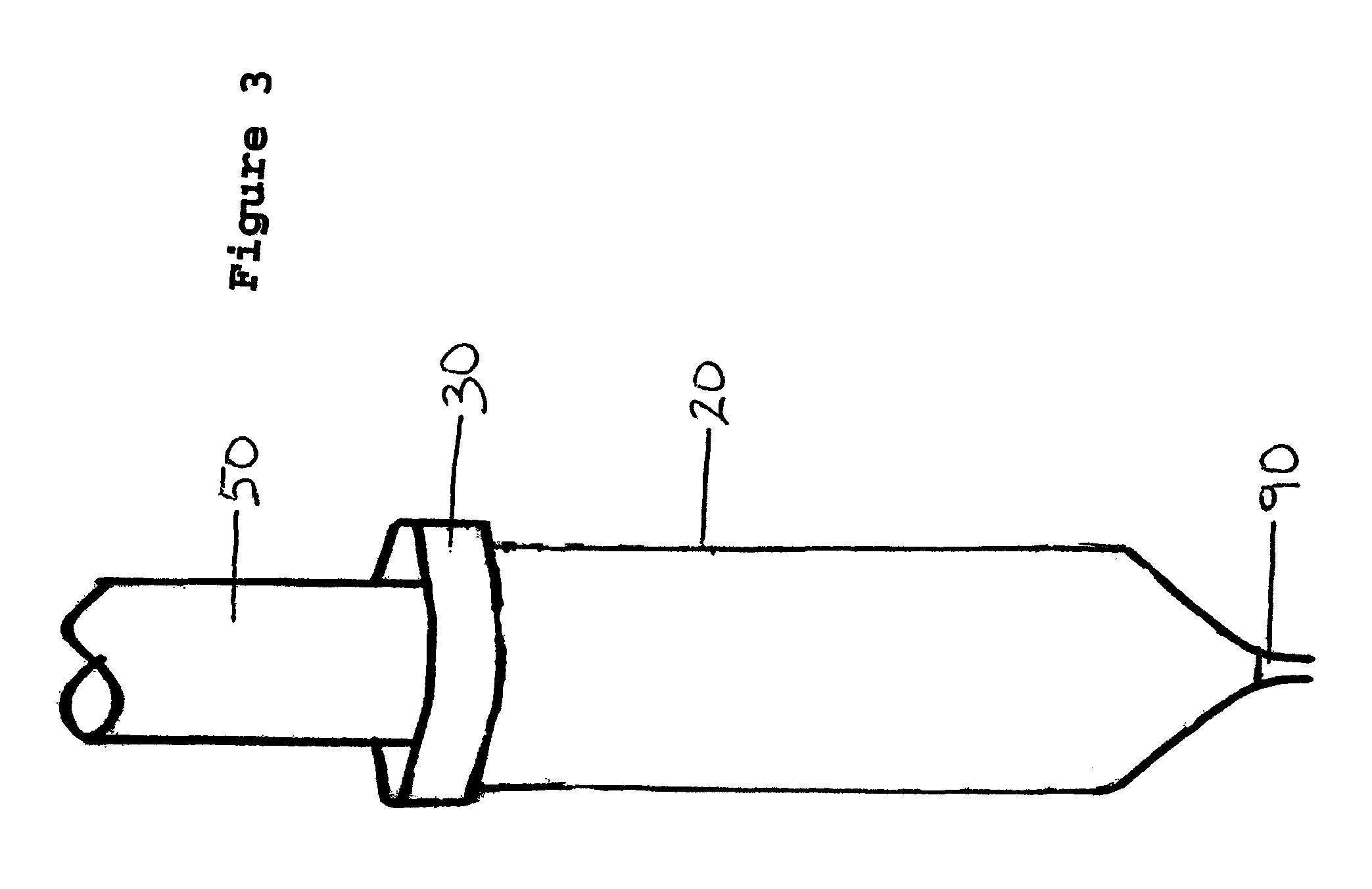
[0021]As shown in FIG. 1, the apparatus 10 includes a drain 70, such as a funnel 72 and tube 73 as shown in FIG. 1 or, as shown in FIG. 3, a drain tube 90 without a funnel for draining material from an open end of an umbilical cord 50. When a child is delivered, the umbilical cord is clampe...


PUM


Abstract

An apparatus and method are provided for harvesting biological material from an umbilical cord. A drain functions to drain the material from the umbilical cord. The apparatus includes a seal member for sealing an open end of an umbilical cord with the drain. A support is provided to support the seal member. An actuator is provided to adjust the engagement of the seal member with the umbilical cord. Moving the actuator relative to the support allows the seal member to twist about the umbilical cord to seal against the umbilical cord to effect drainage of material from the umbilical cord to the drain without leakage.

Description

PRIORITY CLAIM[0001]This application claims priority to U.S. Provisional Patent Application No. 61 / 100,444, filed Sep. 26, 2008, the entire disclosure of which is hereby incorporated by reference.FIELD OF THE INVENTION[0002]The present invention relates to an apparatus and method for collecting biological materials, such as fluids, blood, stem cells, and other cells, from an umbilical cord.BACKGROUND OF THE INVENTION[0003]Umbilical cords contain biological materials that are used in a variety of medical procedures. Specifically, umbilical cords contain fluid, blood, cells and specifically stem cells that may be used in other applications. As the number of procedures using biological materials derived from umbilical cords grows, collecting biological material from umbilical cords has become a commonplace medical practice. A newly-delivered umbilical cord may be used, or a cord may be used after a child is born but before the placenta is delivered. Typically, a medical practitioner wi...

Claims


Application Information

Patent Timeline
Patent Type & Authority Patents(United States)
IPC IPC(8): A61M1/00
CPCA61B5/1411A61B10/0045A61B5/150038A61B5/150366
Inventor KUZYK, ROMAN
Owner KUZYK ROMAN
Learn More