Condensate drain pan for air conditioning system

a technology of air conditioning system and condensate drain, which is applied in the direction of defrosting, heating types, domestic cooling apparatus, etc., can solve the problems of unwanted humidity in the air supplied to an indoor space, and achieve the effects of facilitating condensate drainage, reducing condensate accumulation, and enhancing condensate flow

Active Publication Date: 2005-12-27
ADVANCED DISTRIBUTOR PRODS
View PDF12 Cites 58 Cited by
  • Summary
  • Abstract
  • Description
  • Claims
  • Application Information

AI Technical Summary

Benefits of technology

[0006]In accordance with one aspect of the invention, a portion of the trough between the inner back wall and the outer back wall includes a central hump to facilitate drainage of condensate toward both of the outer side walls. In accordance with another aspect of the invention, the pan is sloped from back to front to conduct condensate to the front part of the pan where the drain opening is located. In accordance with yet another aspect of the invention, a lowermost portion of the trough is defined by a non-flat surface to reduce condensate accumulation in the pan and to enhance condensate flow in the trough.

Problems solved by technology

Further, air flowing through the heat exchanger coil may pick up moisture from excessive water accumulation in the pan, which may result in unwanted humidity in the air supplied to an indoor space.

Method used


Image

  • Condensate drain pan for air conditioning system
  • Condensate drain pan for air conditioning system
  • Condensate drain pan for air conditioning system

Examples


Embodiment Construction

[0019]The best mode for carrying out the invention will now be described with reference to the accompanying drawings. Like parts are marked in the specification and drawings with the same respective reference numbers. In some instances, proportions may have been exaggerated in order to more clearly depict certain features of the invention.

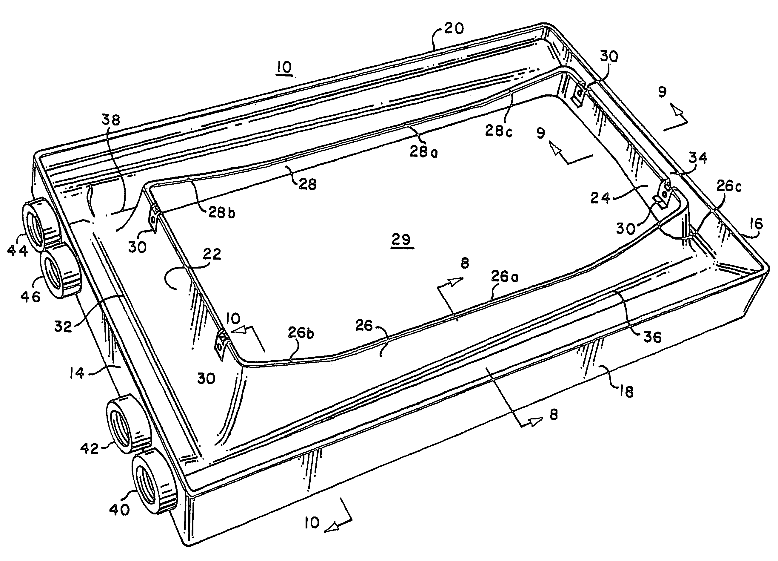
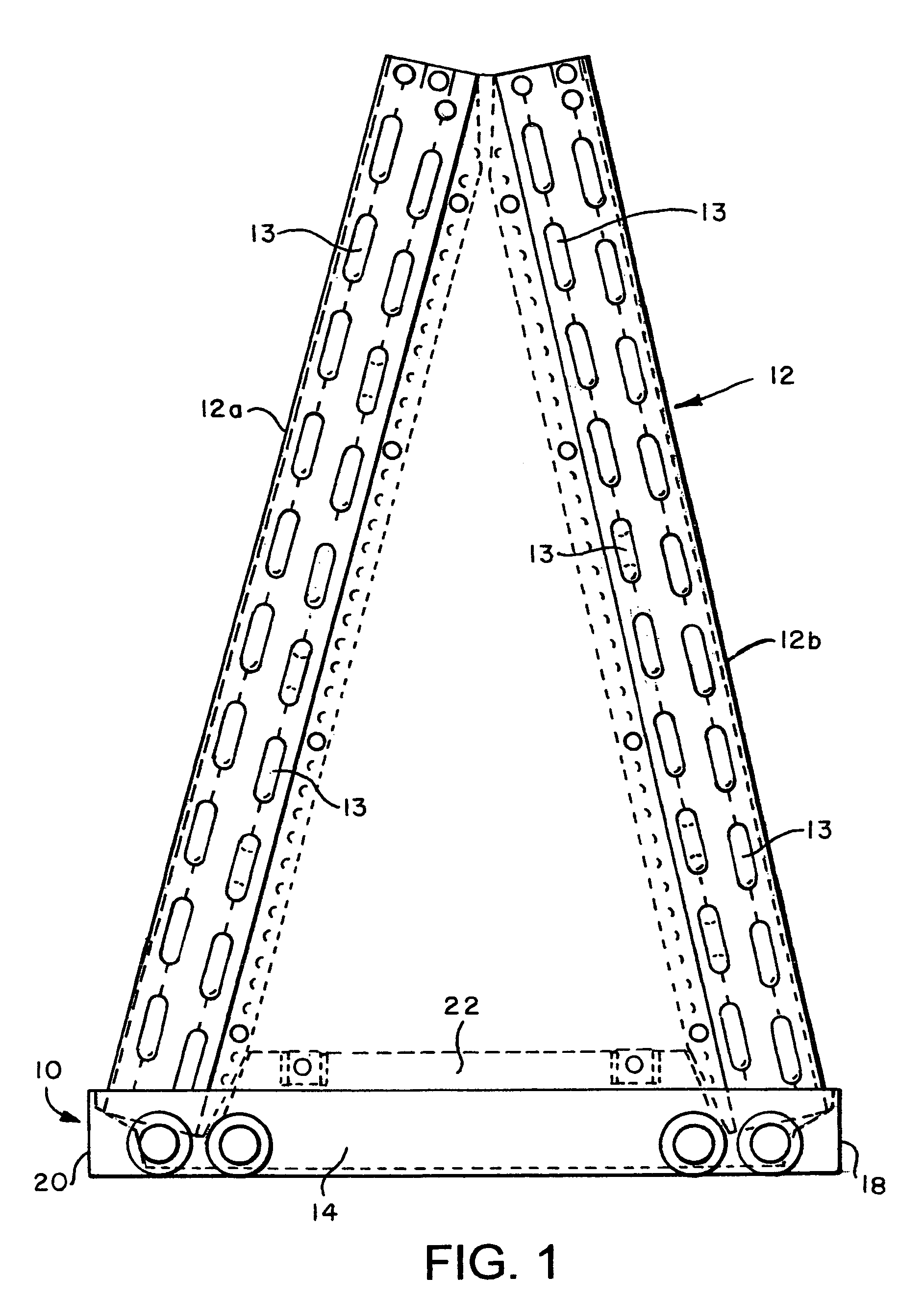
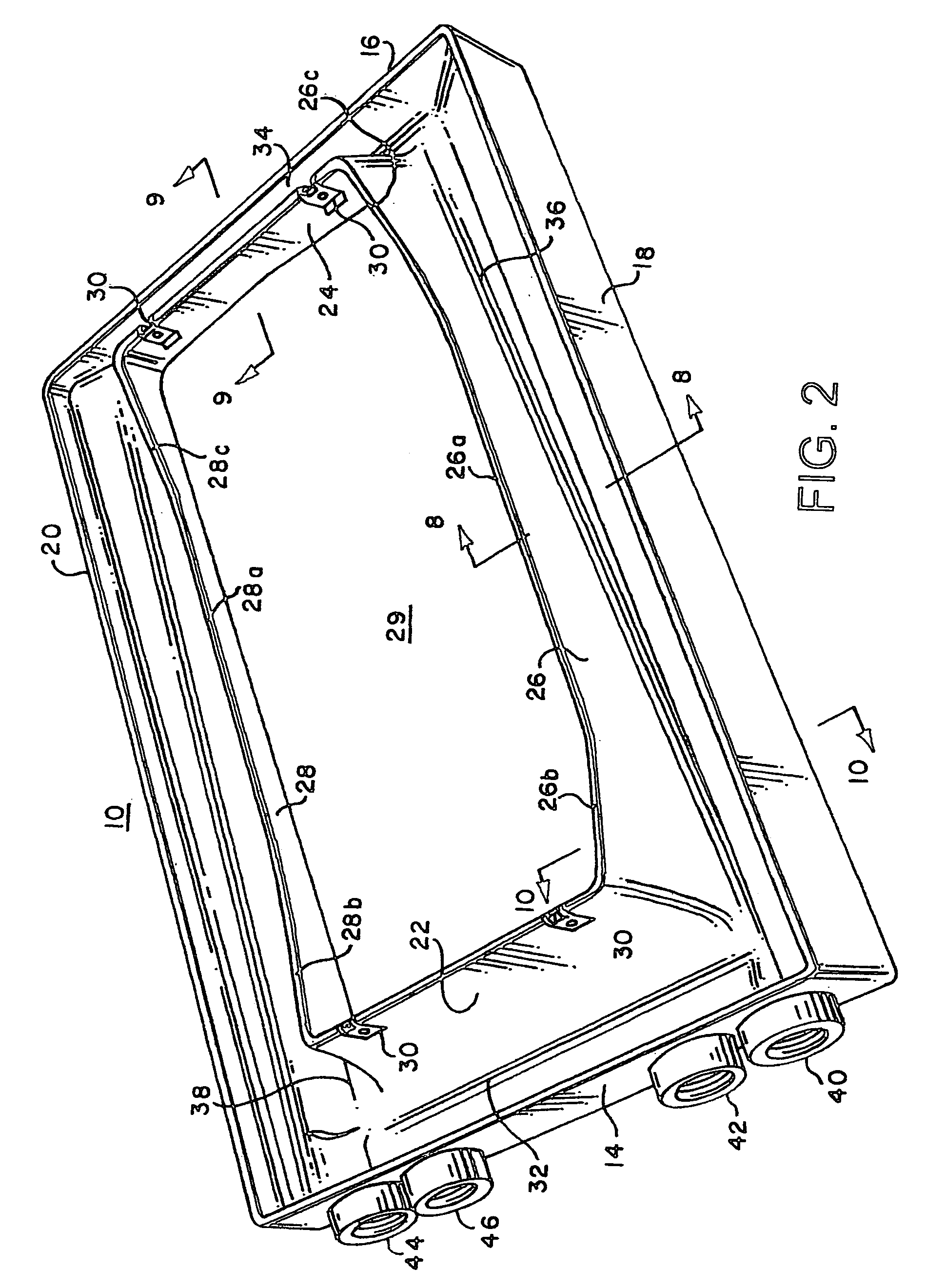
[0020]Referring to FIGS. 1–10, a condensate drain pan 10 according to the present invention is adapted to be positioned underneath a heat exchanger coil 12 in a typical air conditioning system to capture condensate runoff from coil 12 when coil 12 is operated as a cooling coil to cool air flowing through coil 12. For example, coil 12 may be used as an “evaporator” coil, to cool air flowing through coil 12 by evaporating a vapor compression refrigerant flowing inside tubes 13 of coil 12. Coil 12 is depicted in FIG. 1 as a conventional “A-Coil”, comprised of a pair of slabs 12a, 12b coupled together at their respective upper ends and extending downwa...


PUM


Abstract

A drain pan for capturing condensate from a cooling coil in an air conditioning system is configured to facilitate condensate drainage from the pan and to inhibit accumulation of condensate therein. The pan includes troughs for collecting condensate and for channeling the condensate to the front part of the pan where the drain openings are located. A back trough has a central hump to enhance the flow of condensate from the back trough in both directions into opposed side troughs. The side troughs are sloped from back to front to conduct the condensate into a front trough to facilitate drainage from the pan. The lowermost portion of the front trough region is defined by a relatively narrow, non-flat area to reduce the amount of condensate residue in the pan.

Description

TECHNICAL FIELD[0001]This invention relates generally to air conditioning systems and in particular to a drain pan adapted to capture condensate from a cooling coil in an air conditioning system.BACKGROUND ART[0002]Air conditioning systems typically include a blower for circulating air to and from an indoor space to be heated or cooled and apparatus for cooling or heating the circulated air, depending on the mode of operation of the system (i.e., either heating or cooling mode). A device (e.g., a compressor) is also provided for circulating a heat transfer fluid (e.g., a vapor compression refrigerant) between indoor and outdoor heat exchanger coils, whereby the air supplied to the space is cooled or heated. When the system is a conventional air conditioning system (i.e., not a heat pump system), the indoor coil functions as a cooling coil (i.e., as an evaporator when a vapor compression refrigerant is used as a heat transfer fluid) to transfer heat from the air flowing across the ou...

Claims


Application Information

Patent Timeline
Patent Type & Authority Patents(United States)
IPC IPC(8): B65D1/34F24F13/22F25D21/14
CPCF24F13/222
Inventor GOETZINGER, GREGORY T.BECK, CHRISTOPHER D.
Owner ADVANCED DISTRIBUTOR PRODS
Why Eureka
Try Eureka