Pneumatic tire

Active Publication Date: 2013-05-09
SUMITOMO RUBBER IND LTD
View PDF7 Cites 51 Cited by
  • Summary
  • Abstract
  • Description
  • Claims
  • Application Information

AI Technical Summary

Benefits of technology

[0004]It is therefore, an object of the present invention to provide a pneumatic tire in wh

Problems solved by technology

In order to improve wet performance of such pneumatic tire by improving drainage, if the width of a straight main groove is increased, as well known in the art, air existing in a tube formed between the road surface and the main groove in the groun

Method used


Image

  • Pneumatic tire
  • Pneumatic tire
  • Pneumatic tire

Examples


Example

[0034]Embodiments of the present invention will now be described in detail in conjunction with the accompanying drawings.

[0035]According to the present invention, the pneumatic tire comprises a tread portion 2, a pair of sidewall portions, a pair of bead portions each with a bead core therein, a carcass extending between the bead portions, and a tread reinforcing belt disposed radially outside the carcass in the tread portion as usual.

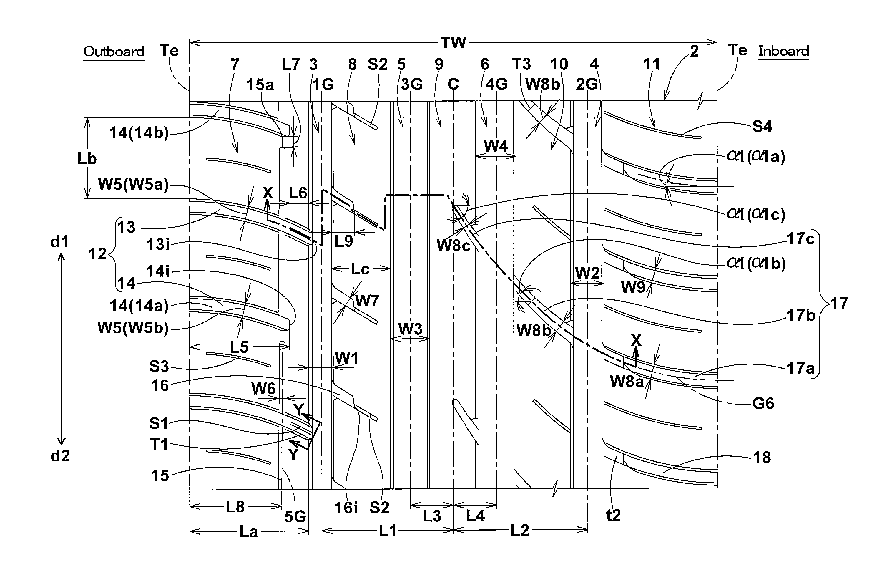
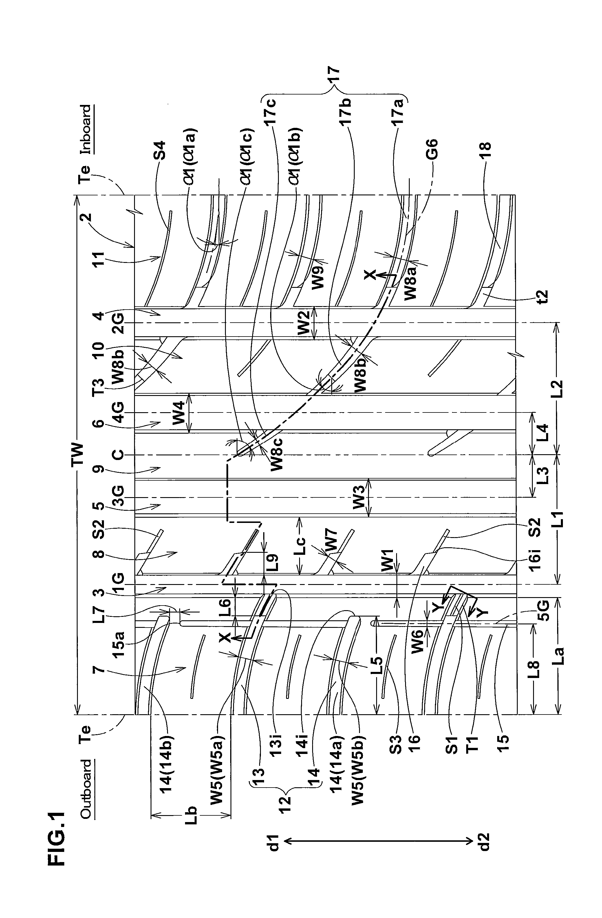
[0036]The tread portion 2 is provided with a tread pattern of left-right asymmetry (asymmetry about the tire equator C) defined by tread grooves. The tread portion 2 has an outboard tread edge 2o to be positioned away from the center of the vehicle body and an inboard tread edge 2i to be positioned close to the center of the vehicle body. For that purpose, the mounting position of the tire is specified. For example, the sidewall portion to be located on outside is provided with an indication such as “outside”, and the sidewall portion to be located on ...


PUM


Abstract

A pneumatic tire has an asymmetric tread pattern. The width of an outboard shoulder main groove (3) is 3 to 4% of the tread width TW. The width of an inboard shoulder main groove (4) is 5 to 6% of TW. The width of an outboard crown main groove (5) is 6 to 7% of TW. The width of an inboard crown main groove (6) is 6 to 7% of TW. In each of the grooves (4, 5, 6), an outboard groove face's angle θ1 is more than an inboard groove face's angle θ2, wherein θ1 is 13 to 19 degrees, and θ2 is 9 to 14 degrees. In the groove (3), an outboard groove face's angle θ3 is 9 to 14 degrees, and an inboard groove face's angle θ4 is 5 to 8 degrees.

Description

BACKGROUND OF THE INVENTION[0001]The present invention relates to a pneumatic tire, more particularly to an asymmetric tread pattern capable of improving the drainage while maintaining the steering stability and noise performance.[0002]In recent years, users of high-performance passenger cars have a preference for pneumatic tires having straight main grooves extending continuously in the tire circumferential direction.[0003]In order to improve wet performance of such pneumatic tire by improving drainage, if the width of a straight main groove is increased, as well known in the art, air existing in a tube formed between the road surface and the main groove in the ground contacting patch of the tire, becomes liable to resonate during running and the noise performance is deteriorated. Further, there is a tendency that the rigidity of the tread portion is decreased and thereby the steering stability is deteriorated.SUMMARY OF THE INVENTION[0004]It is therefore, an object of the present ...

Claims


Application Information

Patent Timeline
IPC IPC(8): B60C11/117
CPCB60C11/1369B60C11/0304B60C2011/0388B60C2011/0353B60C2011/0379B60C2011/0369B60C11/1323B60C2011/0374B60C2011/0381B60C11/125B60C11/01B60C11/03B60C11/13
Inventor MUKAI, TOMOYUKI
Owner SUMITOMO RUBBER IND LTD
Why Eureka
Try Eureka