Sponge type road paving structure for garden and construction method of sponge type road paving structure
A road and sponge technology, applied in the field of garden sponge-type road pavement structure and its construction, can solve the problems of urban waterlogging, affecting road performance, road water permeability, poor drainage performance, etc.
- Summary
- Abstract
- Description
- Claims
- Application Information
AI Technical Summary
Problems solved by technology
Method used
Image
Examples
Embodiment 1
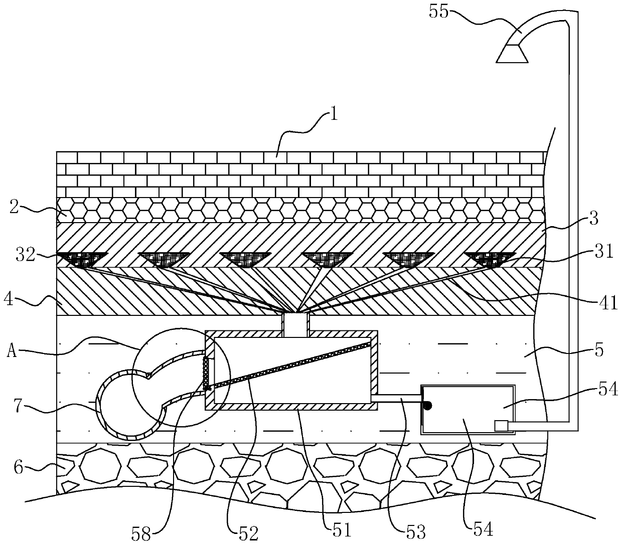
[0037] Embodiment 1: a kind of sponge type road pavement structure with garden, as figure 1 As shown, it includes a permeable surface brick layer 1, a permeable cushion layer 2, a leveling layer 3, a fixed grid layer 4, a base layer 5, and a cushion layer 6 arranged in sequence from top to bottom; the underground urban drainage pipe 7 is arranged at the base layer 5.
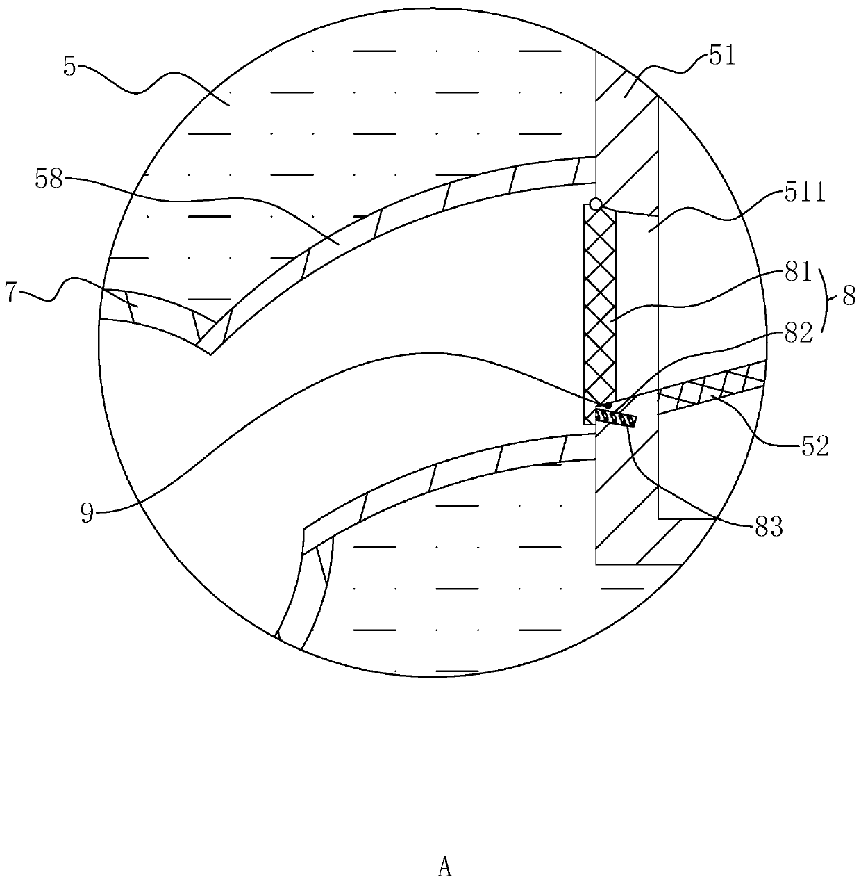
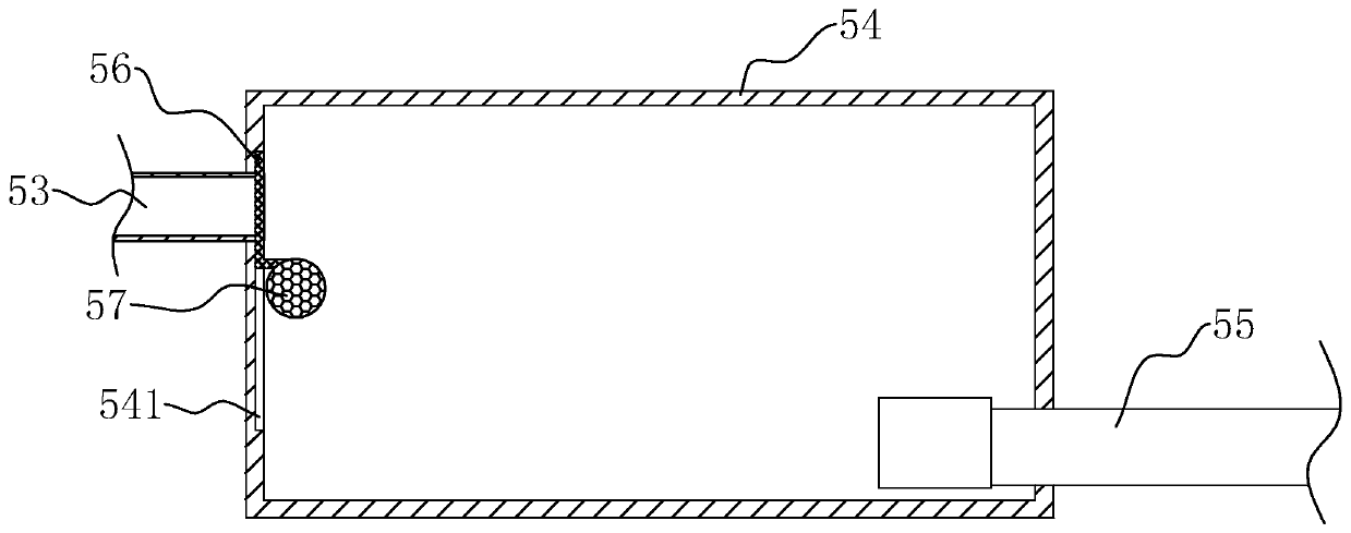
[0038] Such as figure 1 As shown, wherein, a plurality of funnel-shaped water collection holes 31 are provided on the leveling layer 3, and water collection pipes 41 are provided on the fixed grid layer 4, and one end of the plurality of water collection pipes 41 corresponds to the water collection holes one by one. 31 is set and arranged in communication with the water collection hole 31; a water collection box 51 is arranged at the base layer 5, and the water collection pipe 41 is connected to the top of the water collection box 51 after converging; fiber clusters 32 are arranged in the water collection hole 3...
Embodiment 2
[0045] Embodiment 2: a kind of construction method of sponge type road pavement structure for gardens, comprises the following steps:
[0046] S1. Construction control and measurement, after the foundation is dug deep, the site is leveled, and the degree of compaction of the subgrade is above 90%.
[0047] S2. Lay a 50mm thick cushion layer 6 with a particle size of 15-25 on the roadbed, lay a 500mm thick base layer 5 on the base layer 6, and install a water collection tank 51 and a recycling box connected to the water collection tank 51 on the base layer 5 54. The underground urban drainage pipe 7 is installed at the base layer 5, and communicated with the water collection tank 51 through the discharge pipe 58.
[0048] S3. Before laying the fixed grid layer 4, a plurality of water collecting pipes 41 are erected above the base layer 5, and one end of the water collecting pipes 41 is arranged in communication with the water collecting tank 51, and then the fixed grid layer 4 ...
PUM
| Property | Measurement | Unit |
|---|---|---|
| porosity | aaaaa | aaaaa |
Abstract
Description
Claims
Application Information
 - R&D
- Intellectual Property
- Life Sciences
- Materials
- Tech Scout
- Unparalleled Data Quality
- Higher Quality Content
- 60% Fewer Hallucinations
Browse by: Latest US Patents, China's latest patents, Technical Efficacy Thesaurus, Application Domain, Technology Topic, Popular Technical Reports.
© 2025 PatSnap. All rights reserved.Legal|Privacy policy|Modern Slavery Act Transparency Statement|Sitemap|About US| Contact US: help@patsnap.com


