Friction lining for industrial brakes and drive elements and method for producing a friction lining for industrial brakes and drive elements

A friction lining, driving element technology, applied in the direction of friction lining, household components, applications, etc., can solve the problems of increasing wear noise and odor formation, friction lining overheating friction value, interference and other issues

Inactive Publication Date: 2017-02-15
SCHAEFFLER TECH AG & CO KG
View PDF10 Cites 1 Cited by
  • Summary
  • Abstract
  • Description
  • Claims
  • Application Information

AI Technical Summary

Problems solved by technology

The result: localized overheating of the friction lining and the associated disturbance of the friction values, increased wear and possible noise and odor formation

Method used


Image

  • Friction lining for industrial brakes and drive elements and method for producing a friction lining for industrial brakes and drive elements
  • Friction lining for industrial brakes and drive elements and method for producing a friction lining for industrial brakes and drive elements

Examples


Embodiment Construction

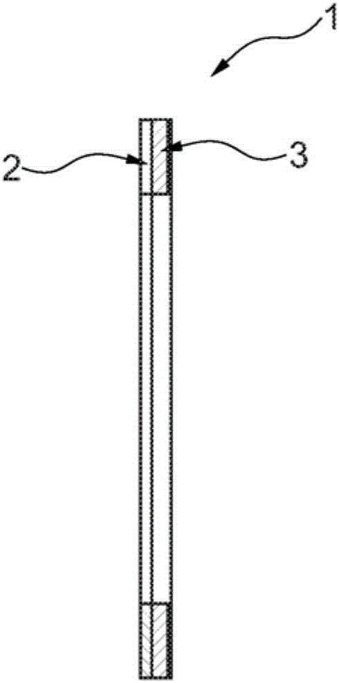
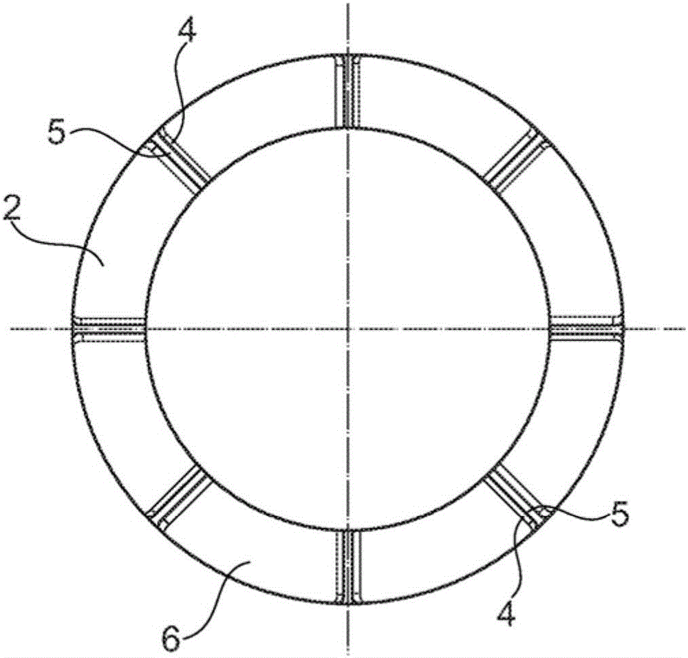
[0022] exist figure 1 An exemplary embodiment of a friction lining 1 according to the invention is shown in FIG. 1 , which is designed to be annular. In side view it can be seen that the friction lining 1 is composed of two layers, namely the friction layer 2 and the carrier layer 3 , which can also be referred to as the base layer. The double-layer friction lining 1 is attached via a carrier layer 3 to a rigid rotor of an industrial brake or a drive element, for example a clutch, when used. The friction layer 2 is a plastic elastomer composition consisting of 0% to 25% elastomer in the form of rubber and 5% to 30% resin. The plastic elastomer composition has a filler content of between 45% and 70%.

[0023] The plastic elastomer composition forming the carrier layer 3 is a composite material consisting of SBR rubber with a proportion of between 10% and 40%. Additionally, between 0% and 20% resin and between 40% and 80% filler material are contained. In the produced state,...


PUM


Abstract

The invention relates to a friction lining for industrial brakes and drive elements, said lining comprising a dual-layer structure, a friction layer (2) being connected to a backing layer (3). In such a friction lining which is particularly suited to industrial applications, the backing layer (3) is inherently resilient and the friction layer (2) and / or the backing layer (3) is / are produced from a synthetic material-elastomer composite.

Description

technical field [0001] The invention relates to a friction lining for industrial brakes and drive elements, said friction lining having a two-layer structure, wherein the friction layer is connected to a carrier layer, and to a method for producing a two-layer friction lining . Background technique [0002] Friction linings in industrial brakes and industrial drive elements such as clutches are used to: hold static loads (holding brakes), brake rotational movements (dynamic brakes) or compensate relative movements (clutches). A two-layer friction material is known from DE 697 26 641 T2, which consists of a fibrous base material. The fibrous base material has a first layer and a second layer, said layers being joined to each other during the wet papermaking process. In this case, the first layer is formed from a friction material comprising fibers and / or filler material and / or friction particles. The second layer of friction material likewise includes fibers and / or filler ...

Claims


Application Information

Patent Timeline
Patent Type & Authority Applications(China)
IPC IPC(8): F16D69/02
CPCF16D69/025F16D2069/005F16D2200/0056F16D2250/0038B29C41/22B29C65/02B29C65/48B29K2009/06B29K2995/007B29K2995/0078B29L2031/16
Inventor 韦拉·鲁埃鲁普弗兰克·施泰因豪尔托尔斯滕·魏尔赫里斯蒂安·斯潘德恩丹尼尔·迈斯纳斯特凡·勒尔
Owner SCHAEFFLER TECH AG & CO KG
Why Eureka
Try Eureka