Seat pan and seat

a seat pan and seat technology, applied in the field of seat pan and seat, can solve the problems of front and rear ends of the weight-loading portion of the seat pan being susceptible to deformation, and achieve the effects of reducing assembly time, absorbing crash energy, and simple manufacturing processing

Active Publication Date: 2019-06-04
BASF AG
View PDF13 Cites 0 Cited by
  • Summary
  • Abstract
  • Description
  • Claims
  • Application Information

AI Technical Summary

Benefits of technology

[0006]An objective of the present invention is to provide a seat pan structure which is light and capable of withstanding passenger's weight on seat and absorbing crash energy, is simple in manufacture processing, saves assembly time and improves in terms of seating comfort.
[0007]According to an aspect of the invention, a seat pan is provided, which is formed from a first thermoplastic composite material into a one-piece pan, the seat pan having a weight loading portion, wherein at least one slot is provided in the area of the weight loading portion of the seat pan, and covering strips are formed by overmolding onto the side edges of straps separated by the slot and extending along at least a portion of the circumference of the slot so as to reinforce the straps, the covering strips being made of a second thermoplastic composite material. By making use of composite materials, the weight of the seat pan is saved, and by functionally incorporating into the one-piece seat pan straps giving soft behavior, assembly time can be saved while spring effect is added, and through covering strips on the side edges of the straps, it enables to increase the stiffness of the straps and control spring factor of the straps. Meanwhile, the seat pan thus made can function well to withstand the weight of passenger and absorb crash energy.

Problems solved by technology

This is because the front and rear ends of the weight loading portion of the seat pan are susceptible to deform when the seat pan is loaded.

Method used


Image

  • Seat pan and seat
  • Seat pan and seat
  • Seat pan and seat

Examples


Embodiment Construction

[0031]The following embodiments will be described with reference to the drawings in which examples of the embodiments are shown. The same reference numbers, if possible, are used throughout the drawings to indicate the same or similar components.

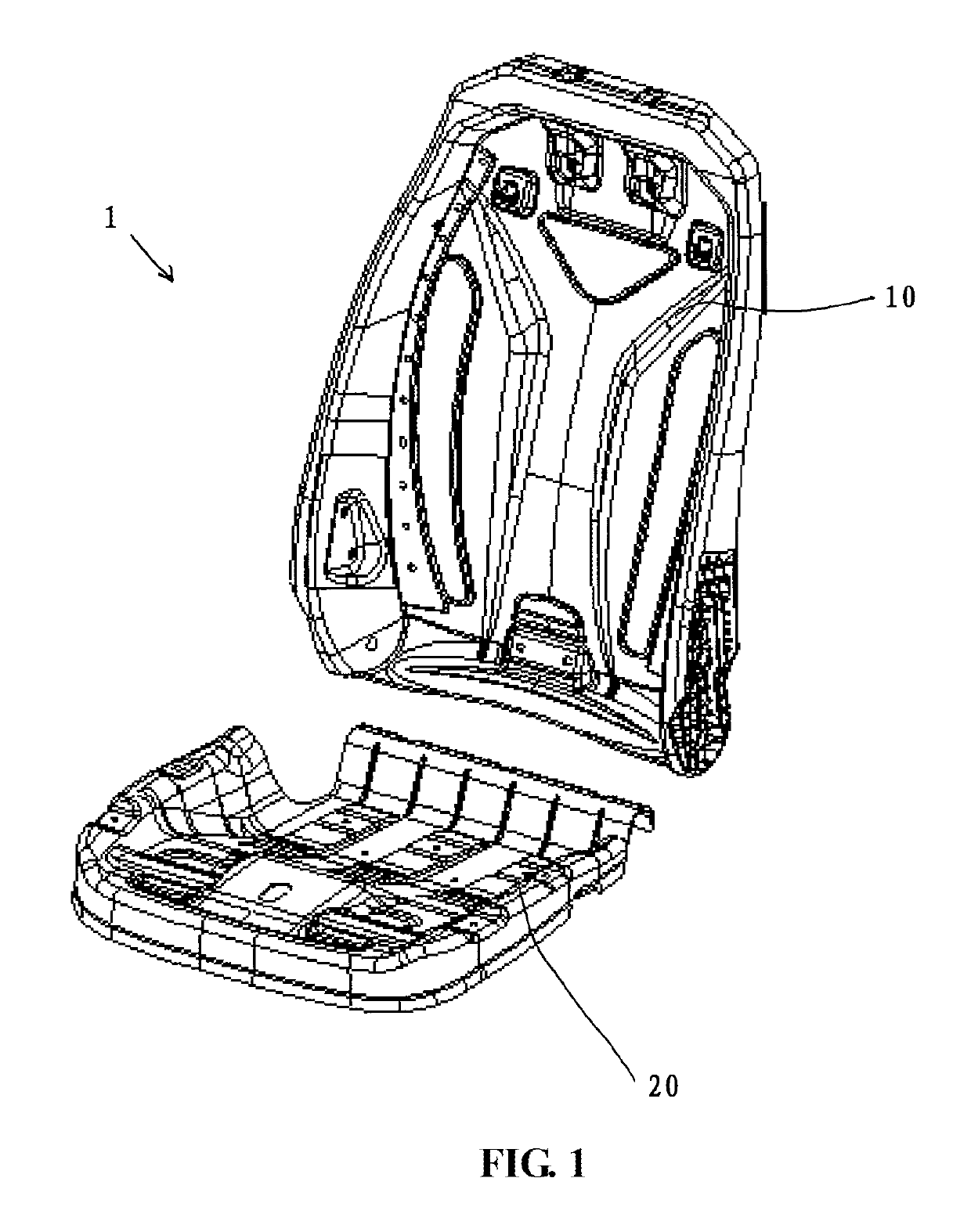
[0032]FIG. 1 is a general view of a seat 1 of the invention, comprising a backrest 10 and a seat pan 20. Generally, a support structure assembly and a height adjustor assembly are provided beneath the seat pan 20. The support structure assembly mainly comprises a bearing tube at the front with respect to a fore-and-aft direction of the seat, a bearing tube at the rear with respect to a fore-and-aft direction of the seat, and lateral bearing racks at the left and right side with respect to a left-and-right direction of the seat.

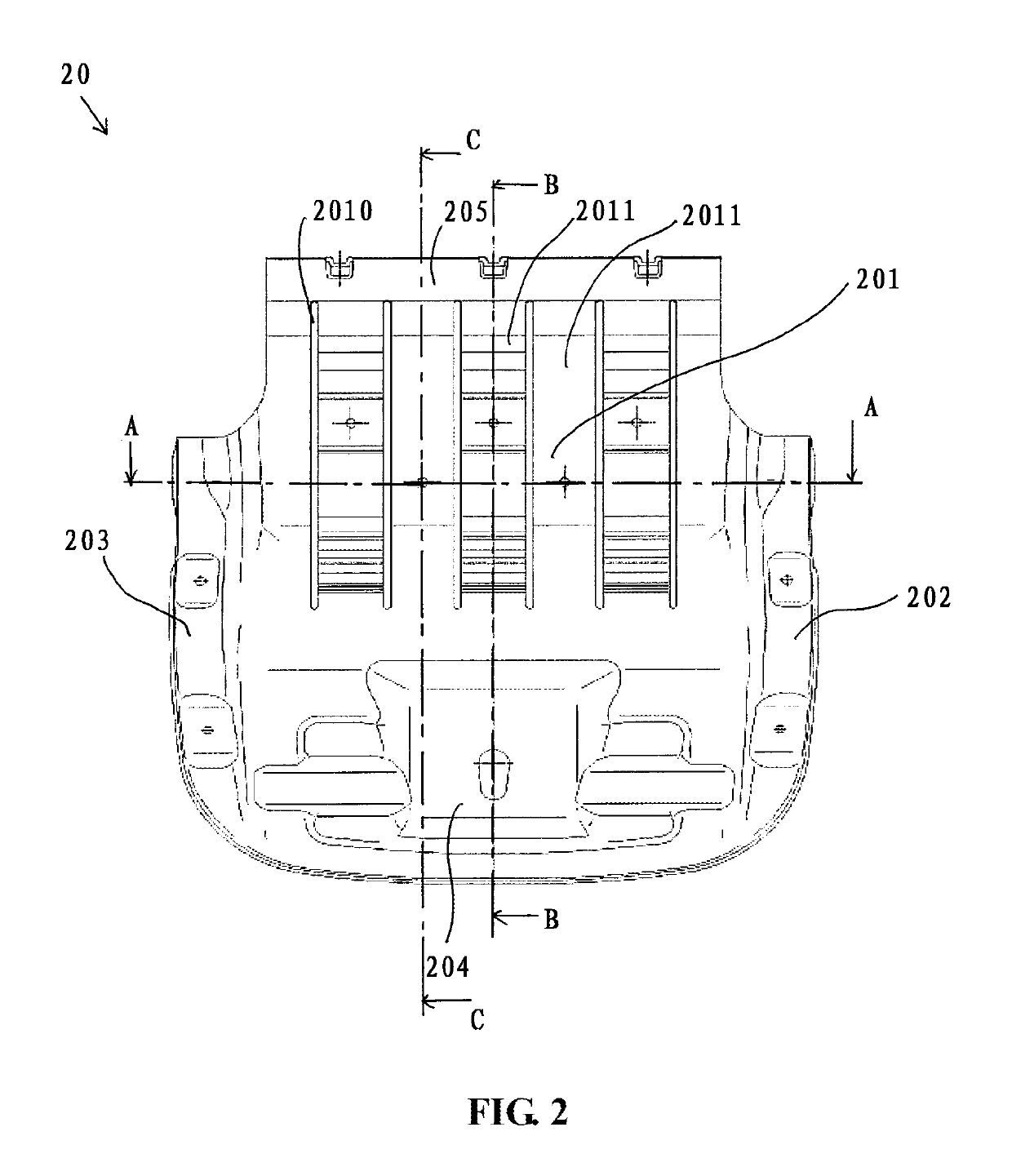
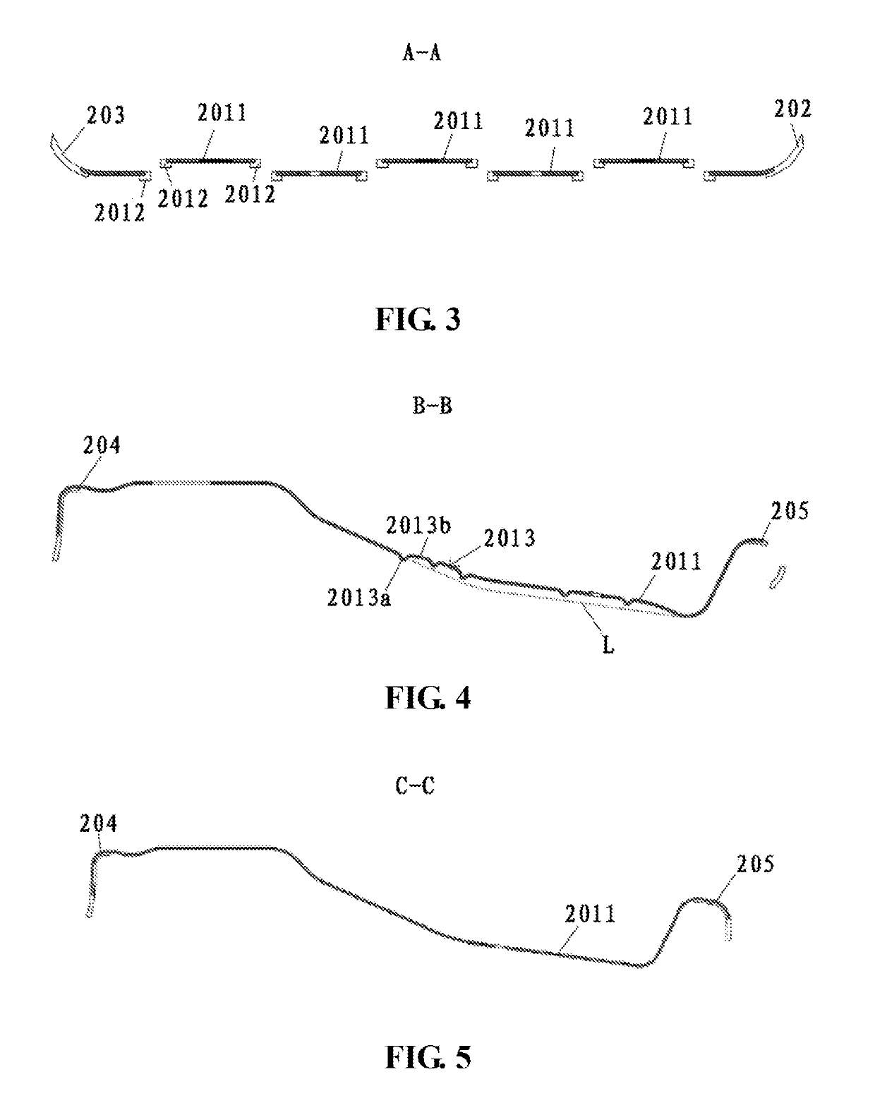
[0033]In the embodiment shown in FIG. 2, the seat pan 20 is made of a first thermoplastic composite material, and formed into one piece in a pan shape, for example, by a thermal processing. The seat pan 20 consists of ...


PUM


Abstract

The invention discloses a seat pan (20), being formed from a first thermoplastic composite material into a one-piece pan, the seat pan (20) having a weight loading portion (201), wherein at least one slot (2010) is provided in the area of the weight loading portion (201) of the seat pan (20), and covering strips (2012) are formed by overmolding on the side edges of straps (2011) separated by the slot (2010) and extending along at least a portion of the circumference of the slot (2010) so as to reinforce the straps (2011), the covering strips (2012) being made of a second thermoplastic composite material. Furthermore, the invention discloses a seat (1) comprising the above seat pan (20).

Description

CROSS-REFERENCE TO RELATED APPLICATIONS[0001]This application is a National Stage of PCT / EP2016 / 050683, which was filed on Jan. 14, 2016. This application is based upon and claims the benefit of priority to Chinese Application No. 201510024410.4, which was filed on Jan. 16, 2015, and to Chinese Application No. 201520033480.1, which was filed on Jan. 16, 2015, the entire contents of both of which are incorporated herein by reference.TECHNICAL FIELD[0002]The present invention relates to a technical field of automobile parts and more specifically to a vehicle internal trim, seat pan and a seat having the seat pan.BACKGROUND ART[0003]During development of automobiles, the seat pan frame of a vehicle seat is one of the most important safety parts. Generally, the seat pan frames of commonly used seats at present are formed by welding, integral punching or pressing and casting sheet metals. The seat pan formed by sheet metals exhibit greater strength, but it is very heavy and therefore usa...

Claims


Application Information

Patent Timeline
Patent Type & Authority Patents(United States)
IPC IPC(8): B60N2/68A47C7/02B60N2/64B60N2/38A61G5/12
CPCB60N2/68A47C7/029A61G5/122B60N2205/30B60N2/646B60N2002/684B60N2/38
Inventor SEO, HEEWONBAUMERT, MARTINCHENG, TSUNG-CHIEHJUN, SANGCHEOLLEE, DAEWOOKANG, SUNGHYUN
Owner BASF AG
Why Eureka
Try Eureka