Electrical brackets for fluorescent bulb

a technology of electric brackets and fluorescent bulbs, which is applied in the direction of electrical equipment, electrical discharge tubes, coupling device connections, etc., can solve problems such as pin damag

Inactive Publication Date: 2015-06-09
HOFFMAN ERVIN
View PDF5 Cites 5 Cited by
  • Summary
  • Abstract
  • Description
  • Claims
  • Application Information

AI Technical Summary

Benefits of technology

[0004]It is an object of the present invention to modify the structure of the existing brackets to eliminate the currently used rotation engagement and activation.
[0005]It is a further object of the present invention to provide such structure with a simple positive engagement of a first pair of pins on one end of the fluorescent bulb and a simple linear movement of the second pair of pins and fluorescent bulb end to complete an electrical connection.

Problems solved by technology

Many problems often manifest themselves with such procedure especially with fixtures having multiple sets of paired brackets for use with multiple bulbs, with restricted access and with ceiling fixtures requiring arm extension installation.
Failure to fully insert the pins may result in damage to the pins when the bulb is rotated with the pins outside of the circular track or if one of the pins is actually outside of the bracket.

Method used


Image

  • Electrical brackets for fluorescent bulb
  • Electrical brackets for fluorescent bulb

Examples


Embodiment Construction

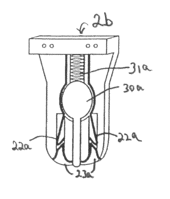
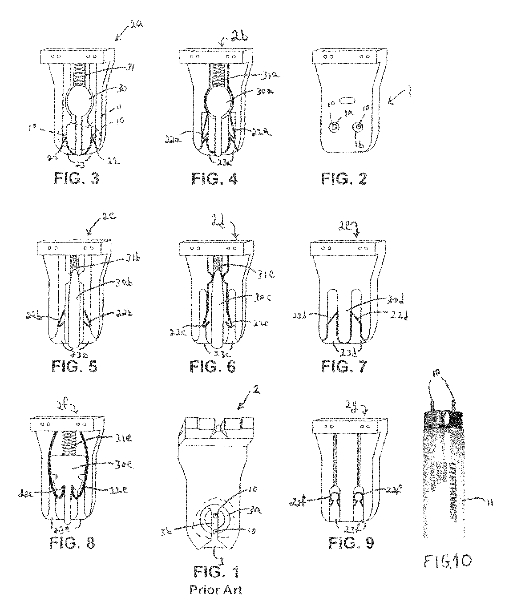
[0017]The Figures provide a contrast between the prior art bracket of FIG. 1 requiring a vertically aligned pin insertion and twisting, with the direct horizontal aperture insertion of the bracket in FIG. 2 and the horizontal upward sliding insertion in the bracket of FIG. 7. FIGS. 3-6 and 8 show various electrical contacts within the bracket and plunger configurations, which permit disengagement of the inserted pin from the spring-loaded supporting and holding metal electrical contact elements for bulb removal. FIG. 9 shows an apertured bracket with sliding slides of simplified structure.

[0018]With more detailed reference to the drawings, FIG. 1 depicts a prior art fluorescent light bracket 2 for use with a fluorescent light bulb 11 with end connector pins 10 such as shown in FIG. 10 (with identical end connectors on both ends of the bulb 11 and identically aligned with each other). A second fluorescent identical light bracket is spaced from the first and facing the first. The spac...


PUM


Abstract

A pair of brackets for a multiple pin fluorescent bulb. A first bracket has two horizontal apertures on an inside face of the bracket and each bracket is sized and spaced from the other to permit insertion engagement and holding of two end pins of one end of the fluorescent bulb. The horizontal apertures permit the other end of the bulb to be vertically moved for engagement with an opposite facing bracket which has two vertical slots with a lower end open access. The vertical slots permit two other horizontally aligned end pins of the fluorescent bulb to be inserted therein by an upward vertical movement. Electrically conductive spring like metal members extend into a path of the vertical slots such that they electrically engage and hold the opposite end pins of the fluorescent bulb. A releasing element pushed the spring like members apart for pin and bulb removal.

Description

FIELD OF THE INVENTION[0001]This invention relates to electrical brackets for long tube type fluorescent bulbs and particularly to such bulbs having multiple end pin connectors such as the ubiquitous 40 watt fluorescent bulbs with double end pin connection elements.BACKGROUND[0002]The design of standard fluorescent bulbs has not changed for decades, not have the brackets and electrical fixtures for such bulbs changed in any significant manner. A typical and standard four foot fluorescent bulb has two pairs of aligned pin connectors on the two ends thereof. Other multiple pin fluorescent bulbs are of various sizes and include 14, 15, 20 and 40 and watt usage (the common four foot bulbs are generally 40 watts). Electrical brackets for such bulbs come in pairs usually fixedly arranged on a fixture. Each one of the members of the bracket pair are identically configured and facingly positioned on the fixtures at a distance slightly larger than the length of a bulb and less than the bulb ...

Claims


Application Information

Patent Timeline
Patent Type & Authority Patents(United States)
IPC IPC(8): H01R33/08
CPCH01R33/0836H01R33/0845
Inventor HOFFMAN, ERVIN
Owner HOFFMAN ERVIN
Why Eureka
Try Eureka