
Auxiliary drive for a trailer

a technology for auxiliary drives and trailers, which is applied in the direction of vehicles, mechanical devices, transportation and packaging, etc., can solve the problems of heavy trailers, considerable pressure forces, and wheel driving,

Inactive Publication Date: 2011-04-26
REICH
View PDF17 Cites 5 Cited by
  • Summary
  • Abstract
  • Description
  • Claims
  • Application Information

AI Technical Summary

Benefits of technology

"The present invention provides an auxiliary drive for trailers, such as caravans, that can be easily fitted without replacing the existing brake system. The auxiliary drive includes a drum with gear teeth and a wheel with gearwheel teeth that can engage with the gear teeth on the drum. The gear teeth are positioned so that the auxiliary drive can be moved laterally, making it easy to engage with the wheel. The drive unit is preferably movable linearly by an actuator. The invention allows for simple engagement with the wheel and ensures reliable engagement in all circumstances. The construction is compact and can be easily fitted to different types of wheels."

Problems solved by technology

It has long been a recognized problem that after uncoupling from a towing vehicle, manoeuvring of heavier trailers in particular constitutes a problem, which can be solved by using relatively small electric motors, which drive the wheels of the trailer.
The problem is, however, that considerable pressure forces are necessary to prevent slipping between the drive rollers and the wheels.
The fact is that driving of the wheels is required most in difficult circumstances in which such wheels are on soggy ground or the like, when the grip between wheel and drive roller will also be far from optimum.
It is felt by some that the pressure of the roller against the tyre can cause damage to the tyre in the long run.
Moreover, such a drive is easily damaged.
Such a structure avoids the problem of failing contact between roller and tyre, but it has the disadvantage that such a system is not easily universally usable.
Moreover, the position of the spring-loaded wheel relative to the chassis constitutes a problem for the positioning of the auxiliary drive.

Method used


Image

  • Auxiliary drive for a trailer
  • Auxiliary drive for a trailer
  • Auxiliary drive for a trailer

Examples


Embodiment Construction

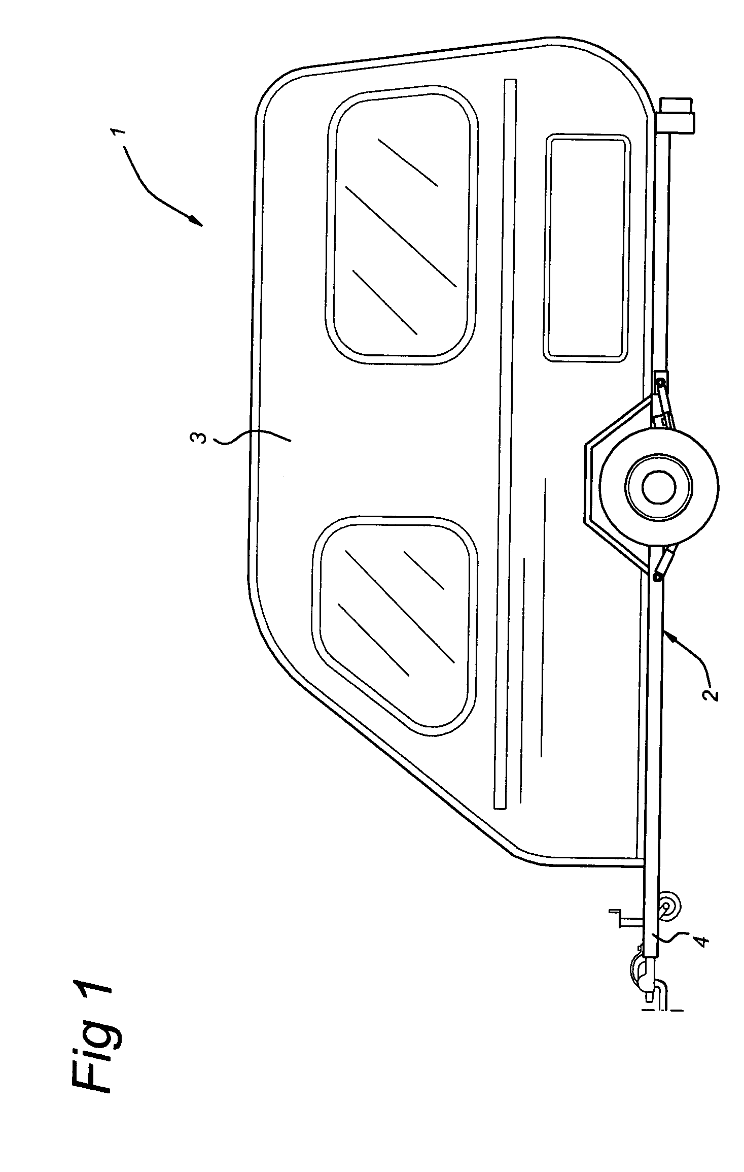
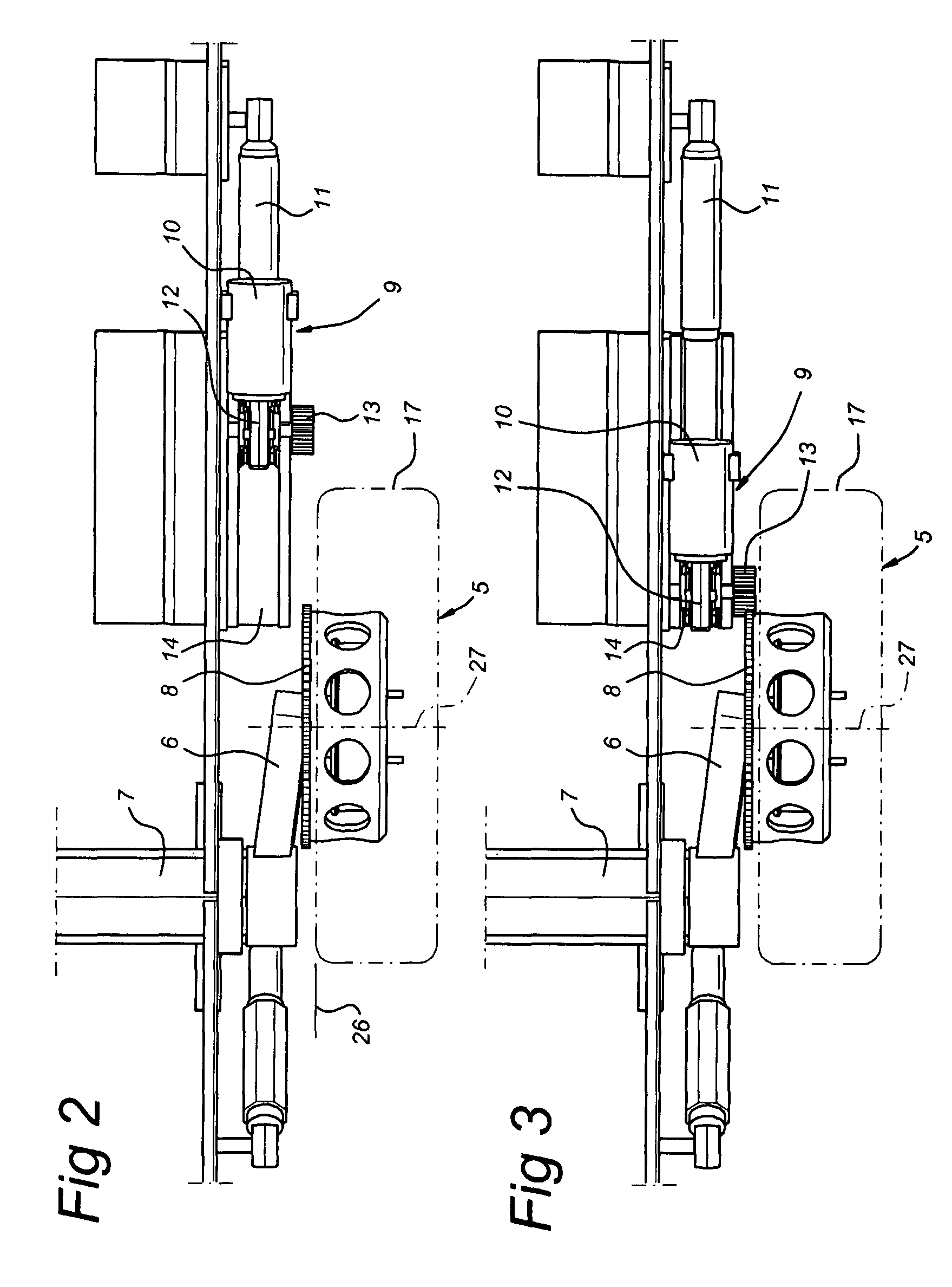
In FIG. 1 a caravan is indicated by 1. This caravan comprises a chassis 2 with a superstructure 3 and a tow bar 4. It should be understood that the present invention can be used for any trailer which in “normal” circumstances is moved by a towing vehicle and in the case of which its own drive is needed only after uncoupling from the towing vehicle. As can be seen from FIG. 2 and on, the caravan is provided with an axle 7 having a suspension arm 6 hinged to the axle. Wheel 5 is connected to suspension arm 6 and is provided with a tyre 17. It is clear from FIG. 5 that a shaft stud 28, around which a conventional brake drum 19 is rotatably fitted, is provided on suspension arm 6. Details of the brake construction present in the brake drum 19 are not shown. Bolts 25, onto which wheel nuts can be screwed in order to fix the wheel 5, extend from the brake drum 19.

According to an aspect of the present invention, an auxiliary part or covering drum 20 is fitted over drum 19. The internal dia...


PUM


Abstract

Auxiliary drive for a trailer such as a caravan. Said drive consists of a drive unit with a gearwheel. Through linear movement of the drive unit relative to the chassis, said gearwheel can be brought into engagement with a ring gear fitted either on the brake drum of a wheel of the vehicle or on an auxiliary part such as a covering drum fitted over said brake drum. The ring gear preferably lies in a plane outside the plane bounded by the inside of the wheel.

Description

BACKGROUND OF THE INVENTIONThe present invention relates to an auxiliary drive for a trailer. Such an auxiliary drive, for example for a caravan, is generally known in the prior art. It has long been a recognized problem that after uncoupling from a towing vehicle, manoeuvring of heavier trailers in particular constitutes a problem, which can be solved by using relatively small electric motors, which drive the wheels of the trailer. In the prior art the use of drive rollers that are connected to the electric motors and engage the tyre of the wheel is generally proposed.The problem is, however, that considerable pressure forces are necessary to prevent slipping between the drive rollers and the wheels. The fact is that driving of the wheels is required most in difficult circumstances in which such wheels are on soggy ground or the like, when the grip between wheel and drive roller will also be far from optimum.It is felt by some that the pressure of the roller against the tyre can ca...

Claims


Application Information

Patent Timeline
Patent Type & Authority Patents(United States)
IPC IPC(8): B62D59/04
CPCF16D65/00B62D59/04
Inventor BENDER, HELMUTHBENDER, STEFFENVAN SCHIE, MICHAEL PETRUS
Owner REICH
Learn More