Vibration absorbing clamp for pipe

a technology of vibration absorbing clamp and pipe, which is applied in the field of clamp for gripping a long component, can solve the problems of insufficient vibration absorbing function, weakened gripping strength, vibration transmission, etc., and achieve the effect of minimizing the risk of pipe gripper and sufficient gripping for

Inactive Publication Date: 2009-11-10
NEWFREY
View PDF11 Cites 30 Cited by
  • Summary
  • Abstract
  • Description
  • Claims
  • Application Information

AI Technical Summary

Benefits of technology

[0012]An object of the present invention is to provide an improved vibration absorbing clamp for a pipe or other long component that is able to achieve a high vibration absorbing function, hold a pipe with sufficient holding strength, and minimize the disconnection of a pipe gripper from a base.
[0014]In this vibration absorbing clamp, vibration between the base and a pipe gripper is effectively absorbed by the vibration absorbing material. The space between the base and the pipe gripper is maintained at a certain interval by thin plates and is filled with a vibration absorbing material. Because the side walls of the base and the sides of a receiver in the pipe gripper are connected to one another only by the thin plates, the vibration absorbing effect between the base and the pipe gripper is improved. Because the pipe or other long component is gripped directly by a hard plastic pipe gripper, the gripping force on the pipe is sufficient.
[0015]In this vibration absorbing clamp, a receiver preferably has nearly vertical sides and a curved bottom for receiving a long cylindrical component such as a pipe. The sides of the pipe gripper extend downward towards the bottom of the base and are integral with sides of a U-shaped frame having a horizontal portion in space between the curved receiver bottom and the base bottom. This minimizes the risk of the pipe gripper becoming detached from the base.
[0016]In this vibration absorbing clamp, a thin plate is formed integrally with the frame and a bridge near the bottom of the base. This maintains a high vibration absorbing effect while increasing the connection strength between the base and the pipe gripper. The size of a space between a side of the receiver and an adjacent side wall of the base is preferably determined by the maximum diameter of a long cylindrical component such as a pipe to be accommodated by the receiver. This restricts the range of movement of a long component such as a pipe. Preferably, the thin plates at the sides of a receiver are connected on an incline at different heights on the side of the receiver and the side wall of the base. This increases the elasticity on the side of the receiver in the pipe gripper while easily accommodating a long component such as a pipe. Preferably, a fixer for receiving and engaging a rod-shaped stud on a support such as a car body is disposed on the base near a pipe gripper. One side of the fixer also forms one side of a receiver in the pipe gripper.

Problems solved by technology

However, the vibration absorbing function is insufficient.
If the soft buffering plastic material is made thicker to improve the vibration absorbing effect, a pipe is directly gripped by the soft buffering plastic material, and the gripping strength is weakened.
However, because the pipe gripper and the base are connected by a thin plate support at the bottom of the pipe gripper and the bottom of the base, vibration is transmitted via the thin plate support.
The thin plate support also weakens the clamp.
This undermines the pipe gripping function of the pipe gripper.
While the connection strength is better than in the first example, the vibration damping leaves room for improvement, like the clamp in Patent Document 2, and the connection strength is insufficient.
However, because the pipe gripper is separate from the base, sufficient force applied to the base lengthwise with respect to the pipe can cause the pipe gripper to detach from the base.

Method used


Image

  • Vibration absorbing clamp for pipe
  • Vibration absorbing clamp for pipe
  • Vibration absorbing clamp for pipe

Examples


Embodiment Construction

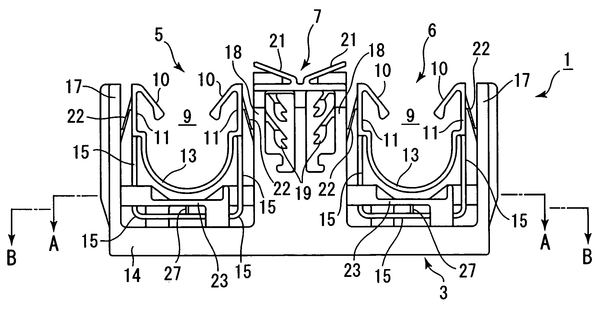
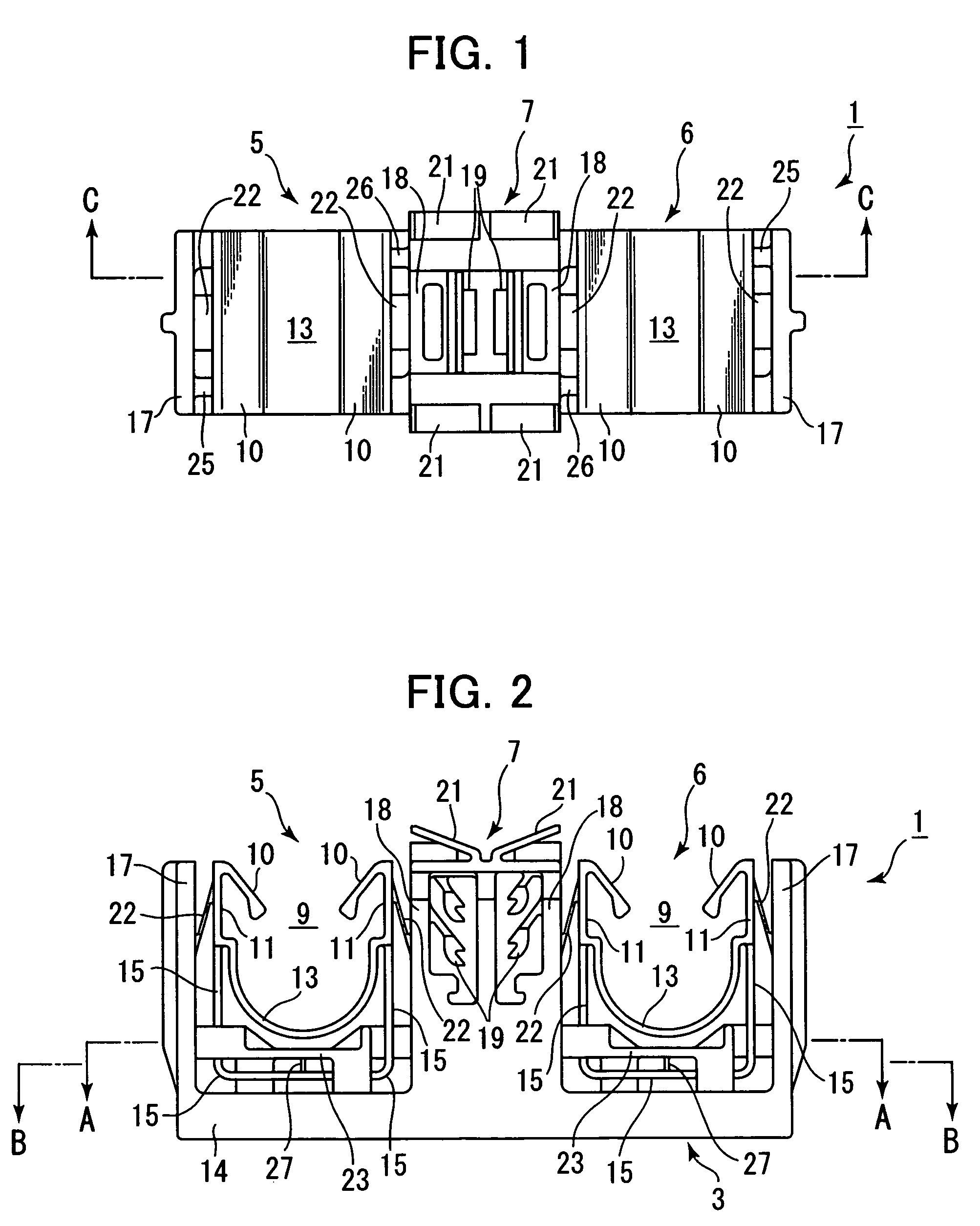
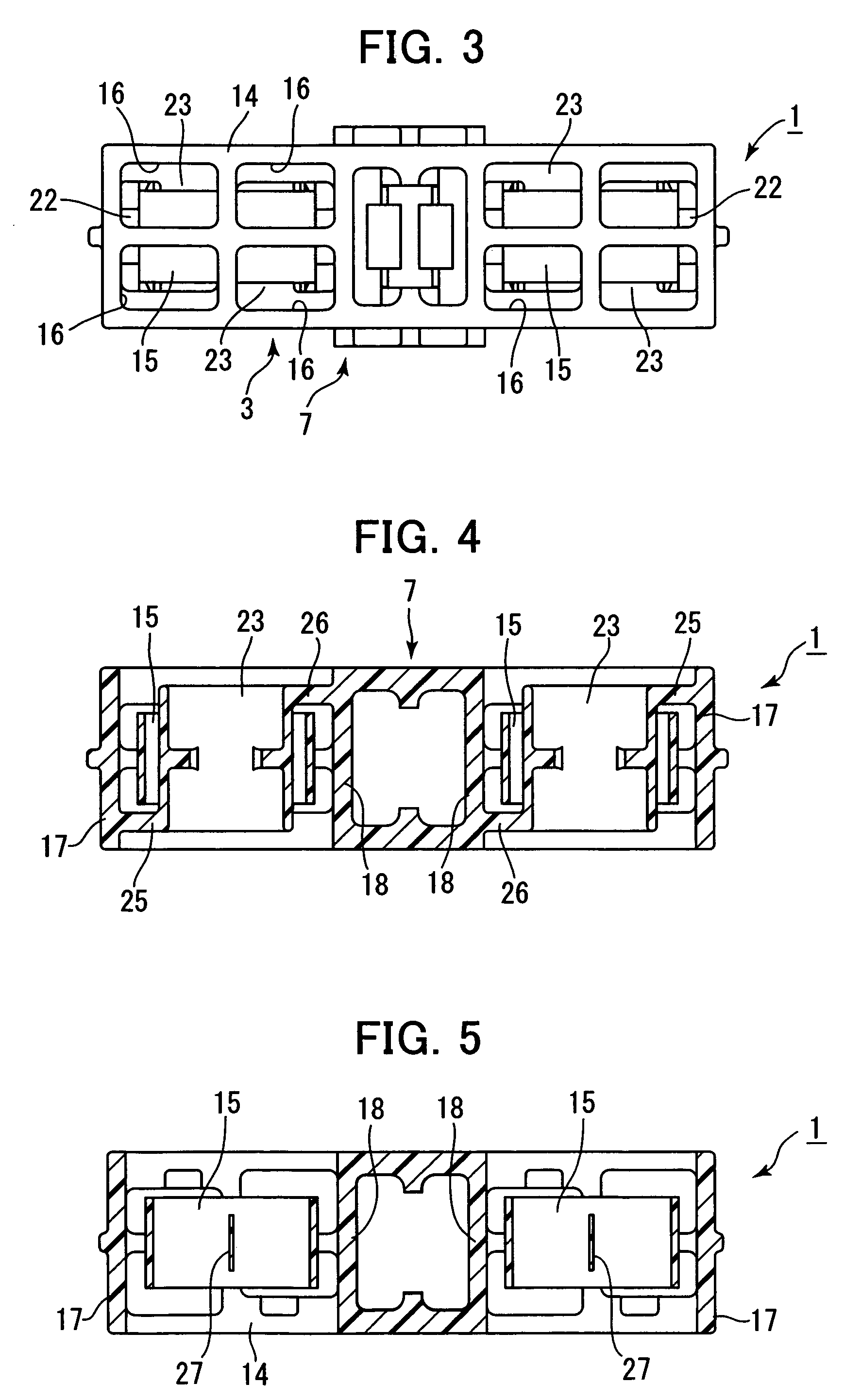
[0033]The following is an explanation with reference to the drawings of a vibration absorbing clamp for a long component such as a fuel pipe, brake line or wire harness in a first embodiment of the present invention. FIG. 1 through FIG. 6 show a primary molded clamp 1 not loaded with a vibration absorbing material. FIG. 7 through FIG. 14 show a secondary molded clamp 1 (final product), which is the primary molded clamp 1 in FIG. 1 through FIG. 6 loaded with a vibration absorbing material. This is the vibration absorbing clamp 2 in the first embodiment of the present invention. FIG. 15 shows a plurality of long components, such as brake lines or fuel pipes, attached to a support such as a car body using the vibration absorbing clamp 2.

[0034]The following is an explanation of the primary molded clamp 1 with reference to FIG. 1 through FIG. 6. The clamp 1 is made of a hard plastic material with sufficient rigidity. The primary molded clamp 1 includes a base 3 and pipe grippers 5, 6 for...


PUM


Abstract

A vibration absorbing clamp comprises a hard plastic base, hard plastic pipe grippers for gripping pipes, and a soft plastic vibration absorbing material disposed between the base and the pipe grippers. Each pipe gripper has a receiver for receiving a pipe and elastic wings allowing the pipe to be pushed into the receiver but not removed. The base has a bottom and side walls spaced from the bottom and sides of the receivers. The sides of the receiver and the side walls of the base are connected only by hard plastic thin plate supports. The spaces formed by the bottoms and sides of the receiver and by the bottom and side walls of the base are filled with vibration absorbing material so as to envelop the thin plate supports.

Description

CROSS-REFERENCE TO RELATED APPLICATION[0001]This application claims the benefit of Japanese Patent Application No. 2005-049205 filed Feb. 24, 2005, incorporated herein by reference.BACKGROUND OF THE INVENTION[0002]The present invention relates to a clamp for gripping a long component such as a pipe or wire harness to attach the long component to a support such as a car body. The invention relates more specifically to a vibration absorbing clamp that is able to prevent transmission of vibrations between a support such as a car body and a long component such as a pipe.[0003]Vibration absorbing clamps are used to attach a long component such as a pipe or wire harness to a support such as a car body, and to prevent transmission of vibrations between the support and the long component. In many vibration absorbing clamps, a soft plastic vibration absorbing material is arranged in a long component gripper to absorb vibrations between the gripper and the long component.[0004]In Unexamined J...

Claims


Application Information

Patent Timeline
Patent Type & Authority Patents(United States)
IPC IPC(8): F16L3/16
CPCF16L3/223F16L55/035F16L3/2235
Inventor KATO, HIROYUKI
Owner NEWFREY
Why Eureka
Try Eureka