Protective cover system

a protective cover and cover plate technology, applied in the direction of instruments, mechanical equipment, transportation and packaging, etc., can solve the problems of affecting the viewing experience of electronic display components, glass or plastic plates are highly susceptible to scratches, and cannot be simply removed or replaced

Inactive Publication Date: 2009-12-08
BRUMWELL LARRY
View PDF1 Cites 42 Cited by
  • Summary
  • Abstract
  • Description
  • Claims
  • Application Information

AI Technical Summary

Benefits of technology

[0007]The present invention relates to a protective cover system. One embodiment of the present invention relates to a multi-layer protective cover system configured to be disposed over a transparent object. Particular embodiments relate to incorporating the system with electronic devices and articles of eyewear that include transparent objects such as display screens and lenses respectively. Each layer of the system includes a transparent member, an adhesion system, and a removal system. The transparent member is shaped to two dimensionally conform or exceed the dimensions of an exposed outer surface of the transparent object. The adhesion system removably couples the transparent member to the transparent object in a manner that does not significantly affect the transparency of the combination. The removal system allows individual layers to be removed without substantially affecting the remaining layers or the transparency of the system. One particular removal system embodiment includes attaching an outer tab to each of the layers. Each tab may be uniquely positioned along the outer edge of each layer to allow a user to peel away one or more top layers without affecting the layers below. In addition, each tab may be uniquely colored and / or numerically labeled to indicate the sequence of layers. A second embodiment of the invention relates to a method for sequentially removing protective layers from a transparent object as each layer becomes damaged or otherwise less transparent.

Problems solved by technology

The glass or plastic plate is highly susceptible to scratches and cracks, which may interfere or prevent a user from viewing the electronic display components.
Unfortunately, the glass or plastic plate cannot simply be removed or replaced without disassembling the entire device.
However, portable electronic devices are exposed to even more circumstances in which the display may be damaged, thereby affecting a user's ability to view the electronic components.
However, certain functionalities of the devices are often inoperable when located in the protective sleeve.
In addition, the protective sleeves increase weight and overall dimensions of the devices, thereby negatively affecting portability.
Therefore, this solution does not adequately solve the problem of display damage to electronic devices.
In addition to electronics, other transparent objects and devices are susceptible to damage that may dramatically affect their usefulness.
Due to their close proximity to a user's eye, small scratches and imperfections are easily noticeable and may affect the performance.
These protective cases do not protect the eyewear during use or in transit to and from the case.

Method used


Image

  • Protective cover system
  • Protective cover system
  • Protective cover system

Examples


Embodiment Construction

[0015]The present invention may be embodied in other specific forms without departing from its spirit or essential characteristics. The described embodiments are to be considered in all respects only as illustrative and not restrictive. The scope of the invention is, therefore, indicated by the appended claims rather than by the foregoing description. All changes that come within the meaning and range of equivalency of the claims are to be embraced within their scope.

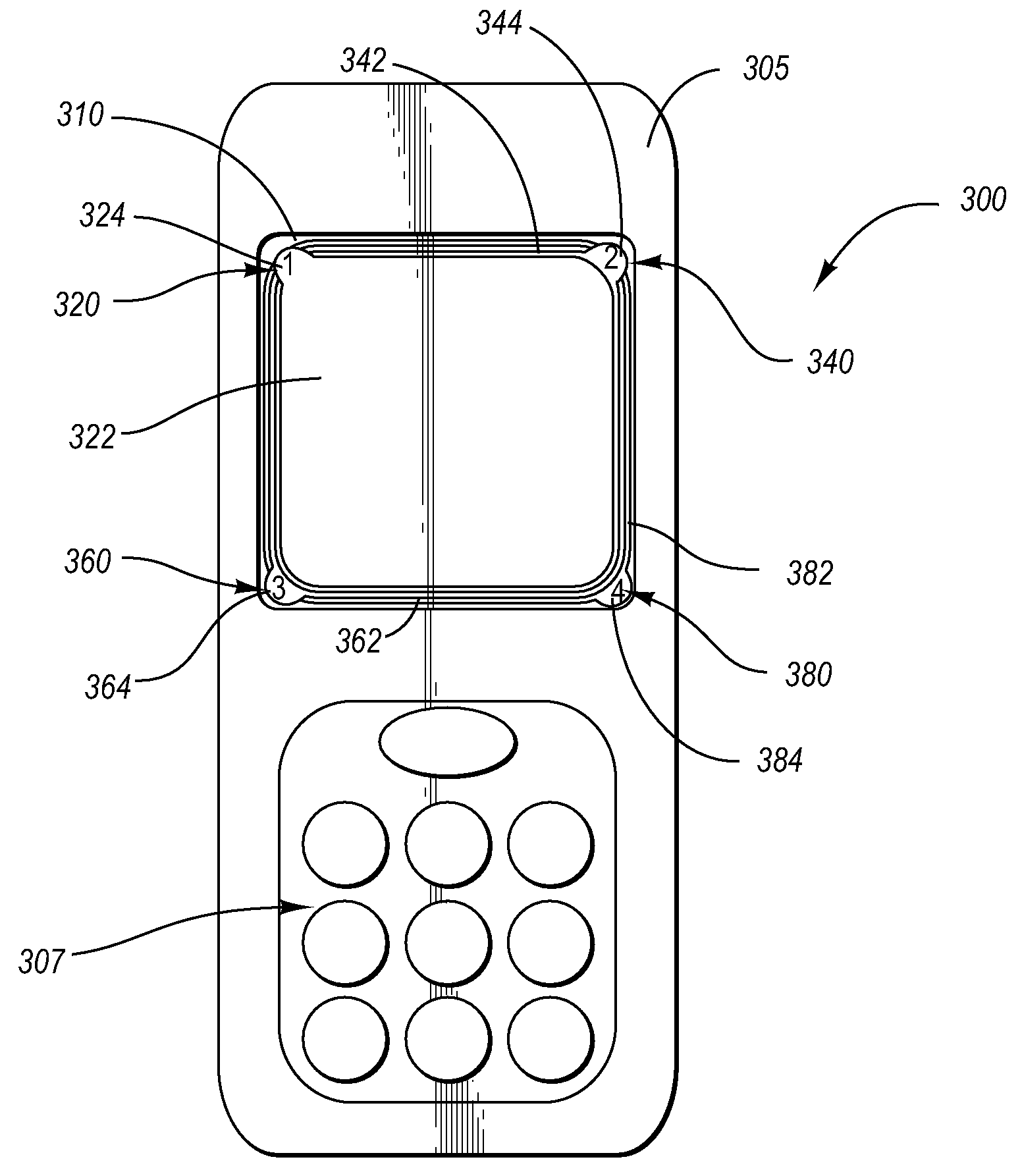
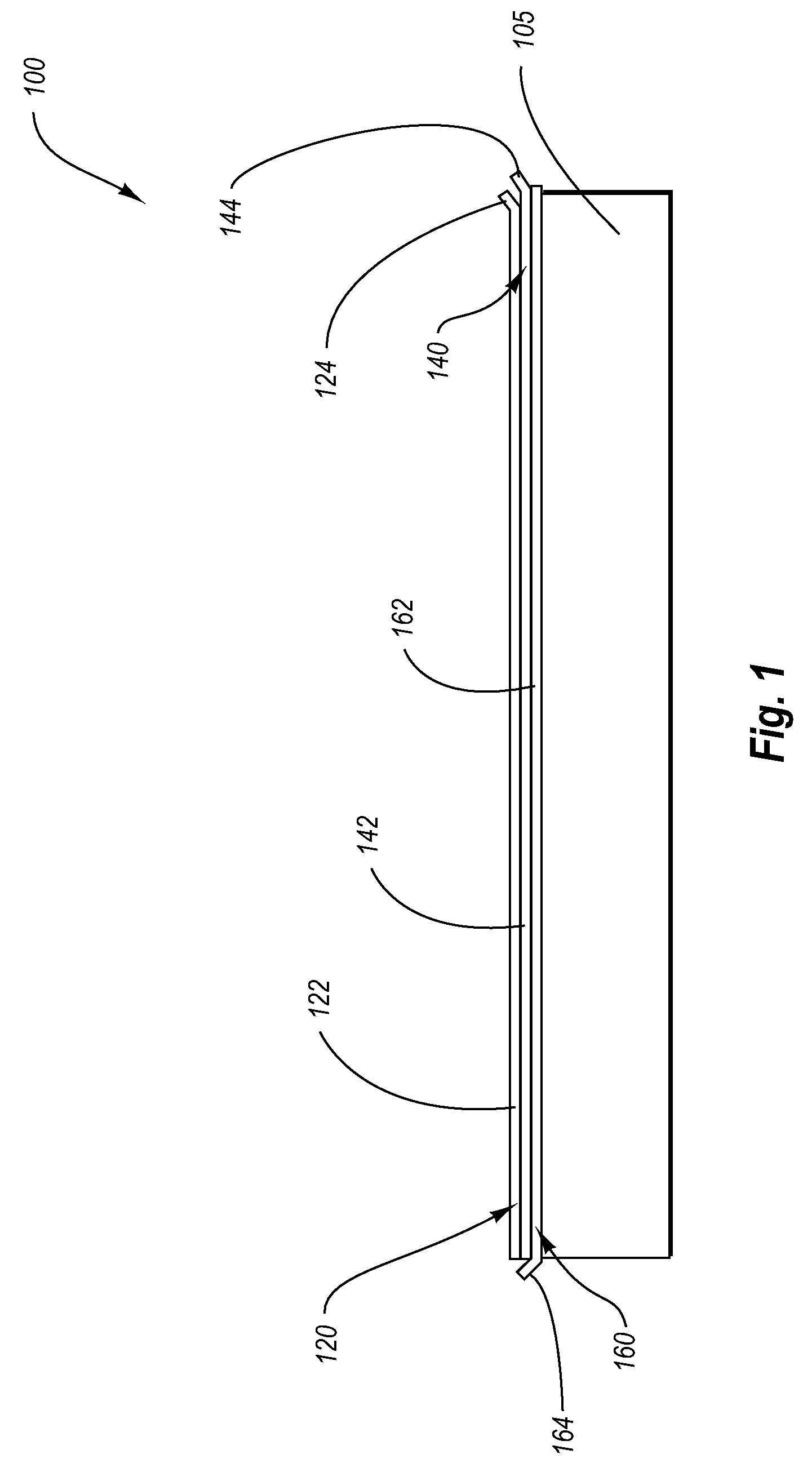
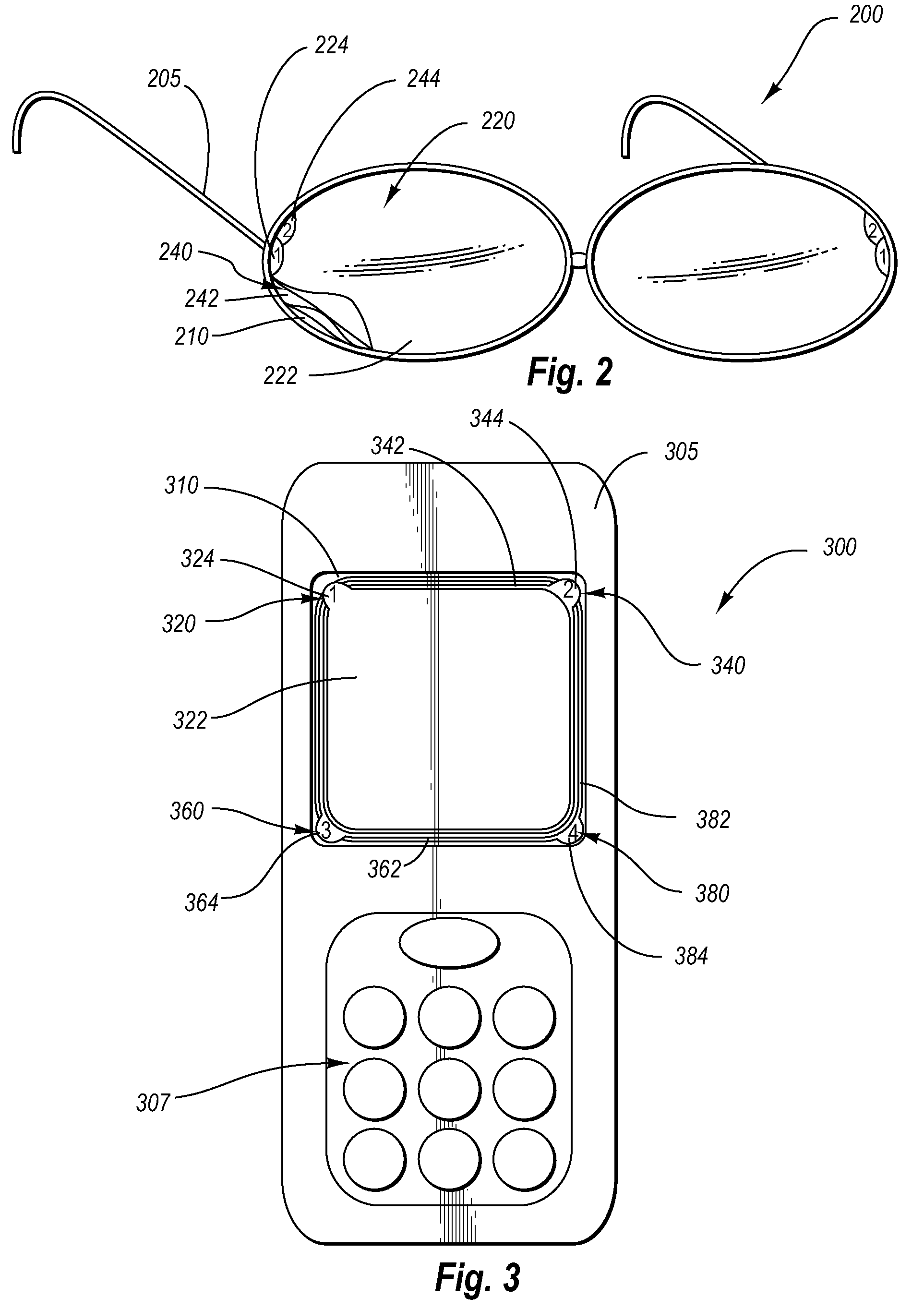
[0016]The present invention relates to a protective cover system. One embodiment of the present invention relates to a multi-layer protective cover system configured to be disposed over a transparent object. Particular embodiments relate to incorporating the system with electronic devices and articles of eyewear that include transparent objects such as display screens and lenses respectively. Each layer of the system includes a transparent member, an adhesion system, and a removal system. The transparent member is shape...


PUM

PropertyMeasurementUnit
transparentaaaaaaaaaa
flexibleaaaaaaaaaa
transparencyaaaaaaaaaa

Abstract

The present invention relates to a protective cover system. One embodiment of the present invention relates to a multi-layer protective cover system configured to be disposed over a transparent object. Particular embodiments relate to incorporating the system with electronic devices and articles of eyewear that include transparent objects such as display screens and lenses respectively. Each layer of the system includes a transparent member, an adhesion system, and a removal system. The transparent member is shaped to two dimensionally conform or exceed the dimensions of an exposed outer surface of the transparent object. The adhesion system removably couples the transparent member to the transparent object in a manner that does not significantly affect the transparency of the combination. The removal system allows individual layers to be removed without substantially affecting the remaining layers or the transparency of the system. One particular removal system embodiment includes attaching an outer tab to each of the layers. Each tab may be uniquely positioned along the outer edge of each layer to allow a user to peel away one or more top layers without affecting the layers below. In addition, each tab may be uniquely colored and / or numerically labeled to indicate the sequence of layers. A second embodiment of the invention relates to a method for sequentially removing protective layers from a transparent object as each layer becomes damaged or otherwise less transparent.

Description

RELATED APPLICATIONS[0001]This application claims priority to U.S. provisional application Ser. No. 60 / 677,868 filed May 5, 2005.FIELD OF THE INVENTION[0002]The invention generally relates to a protective cover system. In particular, the invention relates to systems and methods for protecting vulnerable transparent objects including electronic screens, laminated documents, and eyewear lenses.BACKGROUND OF THE INVENTION[0003]Electronic devices often include one or more display screens for conveying information to a user. These displays generally include a transparent glass or plastic plate for covering the electronic display components. The glass or plastic plate protects the electronics from dust and debris that may otherwise damage the device while allowing a user to still view the electronic display components. The glass or plastic plate is highly susceptible to scratches and cracks, which may interfere or prevent a user from viewing the electronic display components. Unfortunatel...

Claims


Application Information

Patent Timeline
Patent Type & Authority Patents(United States)
IPC IPC(8): B32B17/06B32B43/00
CPCG02B1/105Y10T428/1486Y10T428/149Y10T428/24851Y10T428/2486Y10T428/1471Y10T428/1495Y10T428/1476G02B1/14
Inventor BRUMWELL, LARRY
Owner BRUMWELL LARRY
Why Eureka
Try Eureka