Alternator assembly

a technology of alternators and parts, applied in the direction of synchronous generators with multiple outputs, magnetic circuit shapes/forms/construction, windings, etc., can solve the problem of being exposed to inherent mutual inductan

Active Publication Date: 2010-04-20
CUMMINS GENERATOR TECH LTD
View PDF12 Cites 7 Cited by
  • Summary
  • Abstract
  • Description
  • Claims
  • Application Information

AI Technical Summary

Problems solved by technology

However, a poly-phase system operating on a common magnetic circuit would be exposed to inherent mutual inductance between phases.

Method used


Image

  • Alternator assembly
  • Alternator assembly
  • Alternator assembly

Examples


Embodiment Construction

[0018]For the purposes of promoting an understanding of the principles of the invention, reference will now be made to the embodiments illustrated in the drawings and specific language will be used to describe the same. It will nevertheless be understood that no limitation of the scope of the invention is thereby intended, such alterations and further modifications in the illustrated device, and such further applications of the principles of the invention as illustrated therein being contemplated as would normally occur to one skilled in the art to which the invention relates.

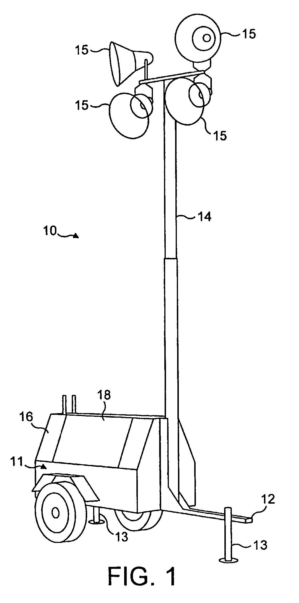
[0019]FIG. 1 shows an exemplary mobile light tower 10 which has a two wheeled trailer 11, a towing hitch 12 and three jacks 13 to support it when stationary. One of the jacks is hidden in FIG. 1. A retractable telescopic boom 14 is mounted on the trailer 11 so as to be upstanding when in use as shown in FIG. 1. In this example, a set of four high intensity lamps 15, such as metal halide lamps, are mounted at th...


PUM


Abstract

The stator (24) of a permanent magnet axial flux alternator comprises two annular stator components which are each wound with a respective two phase winding arrangement (48). Each of the two phase winding arrangements (48) is wound so that there is no mutual inductance between the windings of each phase. Each phase of the two phase winding arrangements (48) wound on the two stator components has a high internal impedance and is for energising a respective high intensity lamp of a light tower.

Description

CROSS-REFERENCES TO RELATED APPLICATIONS[0001]This application is a National Stage filing of International Application PCT / GB2004 / 003760, filed Sep. 2, 2004, claiming priority to United Kingdom Application No. 0320559.8, filed Sep. 2, 2003, entitled “AN ALTERNATOR ASSEMBLY”. The subject application claims priority to PCT / GB2004 / 003760 and to United Kingdom Application No. 0320559.8 and both references are expressly incorporated by reference herein, in their entirety.BACKGROUND OF THE INVENTION[0002]This invention relates to an alternator assembly which can provide an output to a plurality of loads and more particularly, although not exclusively, which is operable to provide an initial voltage output sufficient to initiate conduction of each of a plurality of high intensity lamps to be energised followed by a sustaining voltage output to maintain current flow in each of the lamps after the initial conduction.[0003]U.S. Pat. No. 5,808,450 discloses a lighting system which eliminates t...

Claims


Application Information

Patent Timeline
Patent Type & Authority Patents(United States)
IPC IPC(8): H02K3/00H02K11/00H02K16/00H02K21/24H02K21/48
CPCH02K1/2793H02K3/28H02K21/48H02K11/0094H02K21/24H02K3/46H02K1/12H02K16/00H02K1/2796
Inventor AL-KHAYAT, NAZARJAKEMAN, NIGELMILLS, CLEVELAND
Owner CUMMINS GENERATOR TECH LTD
Why Eureka
Try Eureka