Locator and shutter slat

a technology of locator and shutter, applied in the field of shutters, can solve the problems of slat rattle, loosely articulated slats are known to be noisy, and the shutters of this configuration do not obtain the full benefit of the counterbalance, and achieve the effect of less effor

Inactive Publication Date: 2010-08-31
QUALITAS MFG
View PDF64 Cites 23 Cited by
  • Summary
  • Abstract
  • Description
  • Claims
  • Application Information

AI Technical Summary

Benefits of technology

[0009]According to the present invention, smooth extension and retraction of the roller shutter may be achieved with significantly less effort than required by prior art devices by minimizing the clearance between the engaging track of one shutter slat and the receptacle track of the adjacent shutter slat. There is thus provided a shutter for a building aperture comprising a plurality of shutter slats each having a first face and a second face, and a first end and a second end, and an upper and a lower horizontal edge, which are articulated to form a roller shutter having a first face and a second face, and a first end and a second end. Each shutter slat further has an engaging track and a receptacle track, which run along opposing horizontal edges of each shutter slat. Illustratively, the shutter further comprises two guides, with one guide locatable at either end of the roller shutter.
[0010]Advantageously, flexibility between adjacent slats may be achieved by the alteration of the angle of the engaging track relative to the vertical axis of the shutter curtain. In one embodiment, the present invention provides for the engaging track to be disposed at an acute angle relative to an adjacent part of the body portion or at an angle of less than 180° relative to the vertical axis of an upright shutter slat. In contrast to prior art shutter slats, the angled engaging track of the present invention allows shutter slats to pivot freely while remaining securely disposed within the receptacle track, even when the clearance between engaging and receptacle tracks is decreased. Other features providing flexibility include a concave surface provided on at least part of the articulation surface of the receptacle track or the articulation surface of a guard and providing the engaging track with a hook-shaped member having a curved section that extends for more than 180°. The shutter slat of the present invention may have any combination of these features.
[0011]According to another aspect of the invention, the stability of the connection between engaging track and receptacle track is further improved by providing a guard along the receptacle track. Use of the guard provides protection for the lip and engaging track against damage inflicted on the first face of the roller shutter, such as by a storm or an intruder. Additionally, in some embodiments the security of the shutter slat within the guides is improved by the provision of a receptacle for a retention screw above the main pocket of the receptacle track rather than concentrically with the articulation. The retention screw, which is used for slidably mounting each shutter slat on the first and second guides, is therefore shielded from external forces, including attempts to compromise the integrity of an articulation by forcing two shutter slats apart. In these embodiments, the combination of the receptacle and the guard as provided in the present invention improves stability and security over the use of a concentric receptacle by increasing the force needed to separate an articulation between slats or separate the roller shutter from a guide.
[0012]In yet another aspect of the present invention, the complementary curved profiles of the engaging and receptacle tracks combined with the reduced clearance between shutter slats reduces the noise associated with operation and use of the roller shutter. As the engaging track pivots within the receptacle track, the convex interior of the engaging track contacts the concave interior of the receptacle track, and the former will slide against the latter. In one embodiment of the present invention, the engaging track has no flat (vertical) surfaces to rattle or clank between the first and second portions of the receptacle track.

Problems solved by technology

Shutters of this configuration do not obtain full benefit of the counterbalance, as provided by the torsion spring or by other means.
A further result of this configuration is that the loosely articulated slats are known to be noisy.
In addition, when the roller shutter is deployed, the normal forces of the wind are sufficient to cause the slats to rattle audibly.
One result of this configuration is that if the exposed portion of the c-shaped channel of the lower edge gives way upon exertion of pressure on the articulation, the slats may separate undesirably.
Because the retention of the upper edge by the c-shaped channel is based on a relatively small difference in size, damage to either edge may result in a breach of the curtain.
Even if the channel is bent only slightly, once a gap is formed between an upper edge and a lower edge, the two slats may be pried apart with undesirably slight effort.

Method used


Image

  • Locator and shutter slat
  • Locator and shutter slat
  • Locator and shutter slat

Examples


Embodiment Construction

[0031]FIG. 5 shows a roller shutter 20 according to the present invention, as installed on a building aperture 25 such as a window or door. FIG. 6 depicts one shutter slat according to the present invention, a plurality of which are shown in the roller shutter 20 in FIG. 5. Illustratively, shutter slat 1 is an elongated body of single-ply extruded aluminum having a first end 15 and a second end 16, a body portion 30 bounded by an upper edge 23 and a lower edge 24, and an engaging track 4 and a receptacle track 5.

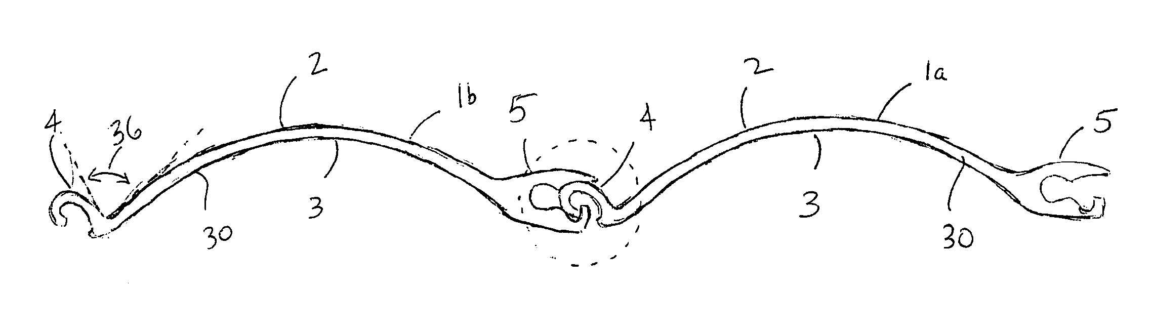
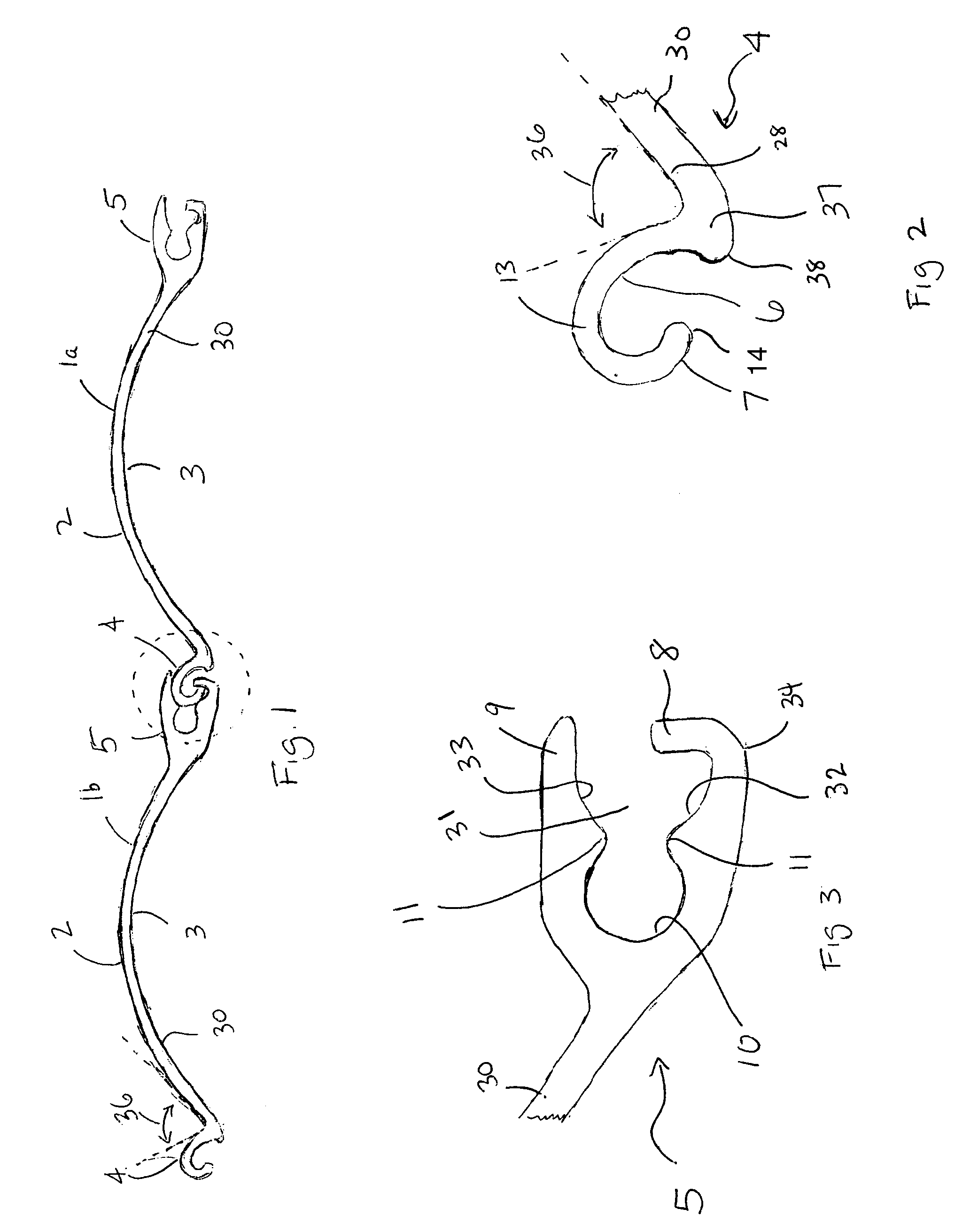
[0032]FIG. 1 is a side view of two shutter slats according to the present invention. Each shutter slat 1a and 1b has a first side 2 and a second side 3, a body portion 30, an engaging track 4, and a receptacle track 5. FIG. 1 shows the engaging track 4 of the right slat 1a engaging receptacle track 5 of the left slat 1b.

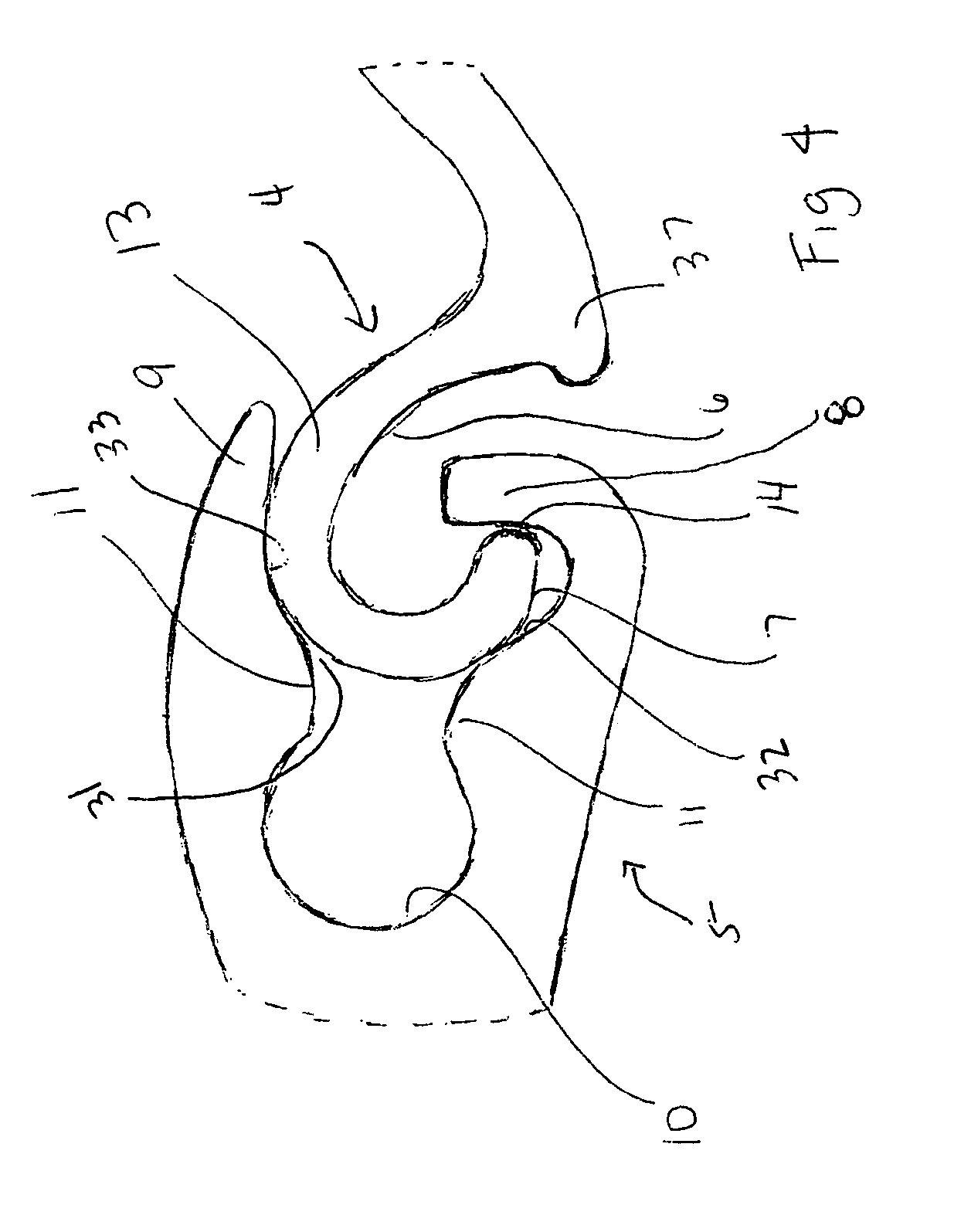
[0033]A detail of engaging track 4 is shown in FIG. 2. Engaging track 4, illustratively located along substantially all of upper edge 23 of shutter slat 1, ...


PUM


Abstract

A rolling shutter and a slat for use in a rolling shutter are provided. The slat comprises an engaging track located at a first edge and a receptacle track located at a second edge. Illustratively, the engaging track has a hook-shaped profile and is disposed at an acute angle relative to an adjacent part of the body portion, is disposed at an angle of less than 180° relative to a vertical axis of the slat, or has a hook-shaped profile that curves for more than 180°, and the receptacle track comprises a lip and a guard defining a space adapted to receive therein an engaging track of an adjacent slat.

Description

[0001]This application is a continuation-in-part of U.S. patent application No. 10 / 802,385, filed Mar. 17, 2004, which is expressly incorporated by reference herein.BACKGROUND OF THE INVENTION[0002]The present invention relates to shutters and in particular to shutters of the roller type. It furthermore relates to a shutter having low clearance and improved retraction capability.DESCRIPTION OF THE RELATED ART[0003]Conventional roller shutters are designed to provide security from break-ins or protection from storms. Because such protection and security may not always be necessary or desired, such as during the day when a retail store is open for business or during fine weather when a homeowner wishes to open windows or enjoy an ocean view, roller shutters are designed to be retractable into a casing in which they are stored. In some examples, to facilitate compact storage, the rigid shutter slats that are designed to resist hurricane winds and burglars also must be capable of confor...

Claims


Application Information

Patent Timeline
Patent Type & Authority Patents(United States)
IPC IPC(8): E06B3/06E06B9/15E06B9/58
CPCE06B9/15E06B9/581E06B2009/1516E06B2009/1533E06B2009/1538E06B2009/1544E06B2009/1566E06B2009/1572
Inventor MILLER, JAMES V.
Owner QUALITAS MFG
Why Eureka
Try Eureka