Mixing drum blade support

a technology of mixing drums and blades, which is applied in cement mixing equipment, chemical equipment and processes, cement preparation equipment, etc., can solve the problems of metal drum internal surfaces tending to wear quickly, metal drum construction is a relatively labor-intensive activity, and the cost of metal drum construction can be relatively high

Active Publication Date: 2010-09-28
MCNEILUS TRUCK & MFG INC +5
View PDF74 Cites 10 Cited by
  • Summary
  • Abstract
  • Description
  • Claims
  • Application Information

AI Technical Summary

Benefits of technology

[0011]Accordingly, it would be advantageous to provide a mixing drum that is cost effective to make and use. It would further be advantageous to provide a mixing drum that is not as labor intensive to produce. It also would be advantageous to provide a mixing drum that is substantially resilient to wear. It would further be advantageous to provide a mixing drum that is capable of withstanding normal loads but is lighter than conventional metal drums. Moreover, it would be advantageous to provide a mixing drum that is not as susceptible to temperature increases as a conventional metal drum. Additionally, it would be advantageous to provide a mixing drum that effectively mixes concrete along the inside surface of the drum. It would also be advantageous to provide components for plastic or composite mixing drums that are suited to the particular properties of the plastic or composite drum and that are lighter and less costly than conventional components for metal mixing drums. It would still further be advantageous to provide a mixing drum that includes any one or more of these or other advantageous features.

Problems solved by technology

First, the construction of metal drums is a relatively labor intensive activity that involves rolling steel sheets into conical portions and cylinders and then coupling the different portions together to form the outer shell of the drum.
Because of the extensive labor required in performing these and other operations, the cost to construct a metal drum can be relatively high.
Second, the internal surfaces of a metal drum tend to wear quickly due to the abrasion on the metal by the concrete, which is increased in the areas where there are abrupt changes in the inner surface of the drum.
Thus, the areas in which the mixing blades are welded or bolted to the shell of the drum tend to be areas of increased abrasion that wear rapidly.
Third, metal drums can be relatively heavy due to the weight of the metal used in the construction of the drum.
Thus, a truck having a heavier drum may not be able to carry as much payload as a similar truck that has a lighter drum, increasing the long-term operating costs of the truck.
This additional heat retained by the drum tends to decrease the time during which the concrete begins to set.
Thus, the distance over which concrete can be moved within mixing trucks that have metal drums is limited.
However, while this may improve the wear and mixing characteristics of the traditional metal drum, the coating adds to both the weight of the drum and the costs of manufacturing the drum.
Moreover, while reinforced plastic mixing blades have been used in such coated medal drums, the additional step of attaching the mixing blade to the drum requires an additional manufacturing step.
However, like the metal drum, the additional step of attaching the mixing blades adds to the cost of manufacturing the drum.
Due to the differences in the material properties and characteristics of a metal drum and a polymer or composite drum, some devices and components employed in conventional drums will not work effectively with a composite drum.
For example, components such as hatches and drive ring assemblies traditionally used with concrete drums are not compatible with a plastic or composite drum.
Moreover, such conventional components tend to be relatively heavy and expensive to manufacture.

Method used


Image

  • Mixing drum blade support
  • Mixing drum blade support
  • Mixing drum blade support

Examples


Embodiment Construction

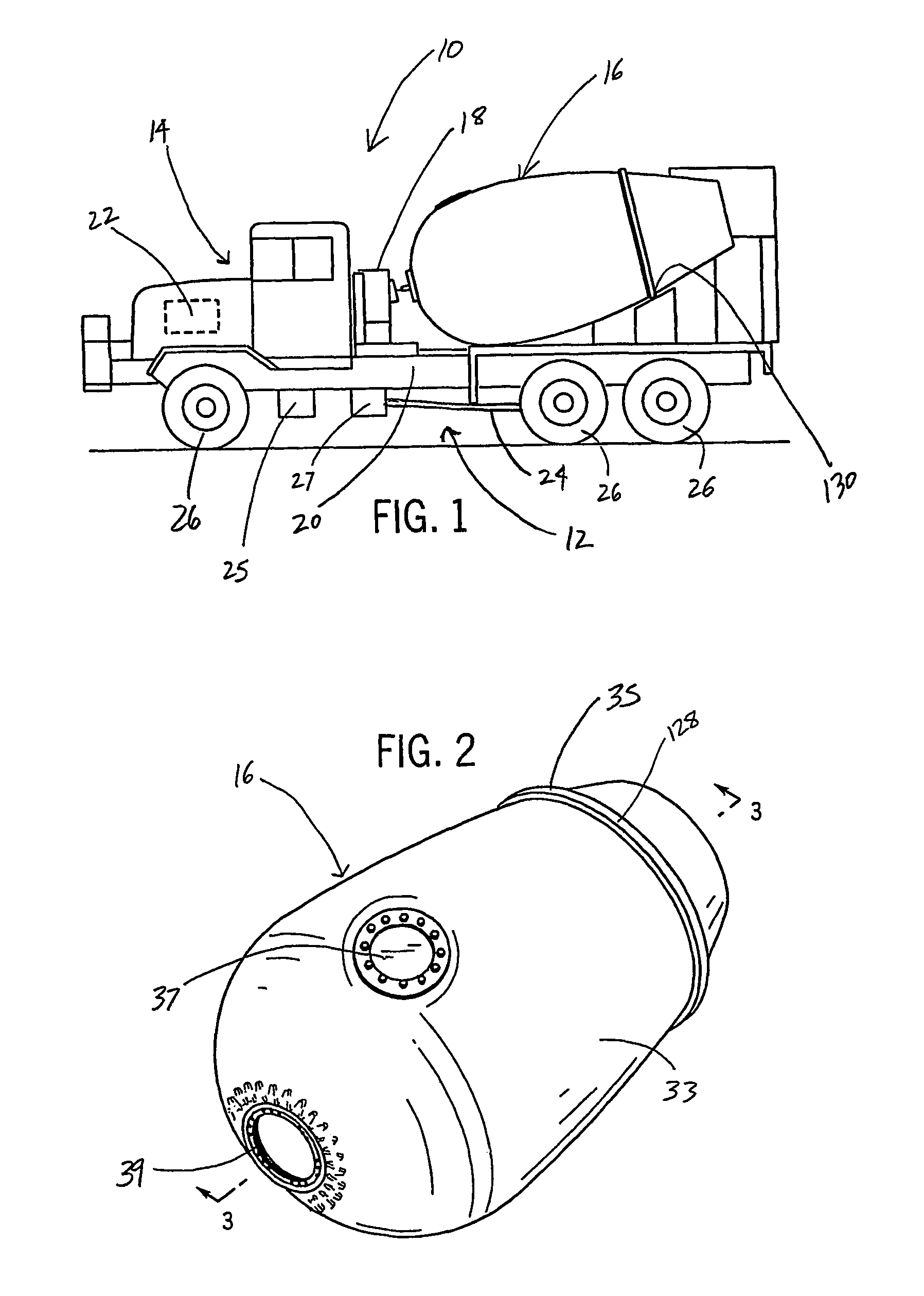
[0027]FIG. 1 is an illustration of a concrete mixing truck 10, which includes a chassis 12, a cab region 14, a mixing drum 16, and a mixing drum drivetrain 18. Chassis 12 includes a frame 20, a power source 22, a drivetrain 24, and wheels 26. Frame 20 provides mixing truck 10 with the structural support and rigidity needed to carry heavy loads of concrete. Power source 22 is coupled to frame 20 and generally comprises a source of rotational mechanical energy which is derived from a stored energy source. Examples include, but are not limited to, an internal combustion gas-powered engine, a diesel engine, turbines, fuel cell driven motors, an electric motor or any other type of motor capable of providing mechanical energy.

[0028]For purposes of this disclosure, the term “coupled” means the joining of two members directly or indirectly to one another. Such joining may be stationary in nature or moveable in nature. Such joining may be achieved with the two members or the two members and ...


PUM

PropertyMeasurementUnit
widthaaaaaaaaaa
heightaaaaaaaaaa
lengthaaaaaaaaaa

Abstract

A heavy duty rotary concrete mixing drum (16) for coupling to a vehicle (10) having a powered drivetrain (18) for rotating the drum comprises a wall and at least one projection (32). The wall (33) includes an inner surface (34) defining a volume and an outer surface (36). The at least one projection is coupled to the wall and extends from the inner surface of the wall. The projection includes a body and a support member (48) disposed within the body.

Description

CROSS-REFERENCE TO RELATED PATENT APPLICATIONS[0001]The present application is related to co-pending International PCT Patent applications entitled MIXING DRUM BLADE by Anthony Khouri and William Rodgers, MIXING DRUM by Anthony Khouri and Peter Saad, MIXING DRUM HATCH by Anthony Khouri, William Rodgers, and Peter Saad, and MIXING DRUM DRIVE RING by Vadim Pihkovich filed concurrently herewith, the full disclosures of which are hereby incorporated by reference.[0002]The present application is also related to International Patent Application Ser. No. PCT / AU00 / 01226 filed on Oct. 9, 2000 by William Rogers entitled VEHICLE MOUNTED PLASTICS DRUM FOR CONCRETE MIXING AND METHODS OF MANUFACTURE THEREOF, and International Patent Application Ser. No. PCT / AU03 / 00664 filed on May 31, 2003 by Anthony Khouri entitled VEHICLE MOUNTED CONCRETE MIXING DRUM AND METHOD OF MANUFACTURE THEREOF, the full disclosure of which are hereby incorporated by reference.BACKGROUND OF THE INVENTION[0003]The present ...

Claims


Application Information

Patent Timeline
Patent Type & Authority Patents(United States)
IPC IPC(8): B28C5/42B28C5/08B28C5/20B29C45/14B29C70/30
CPCB28C5/0831B28C5/2054B28C5/421B28C5/4268B29C70/30B29C45/14
Inventor KHOURI, ANTHONY J.
Owner MCNEILUS TRUCK & MFG INC
Why Eureka
Try Eureka