Composite material for turbine support structure

a technology of composite materials and support structures, applied in the field of composite materials, can solve problems such as leakage that is detrimental to turbine performance and turbine malfunction

Inactive Publication Date: 2010-11-02
GENERAL ELECTRIC CO
View PDF2 Cites 24 Cited by
  • Summary
  • Abstract
  • Description
  • Claims
  • Application Information

AI Technical Summary

Problems solved by technology

Tip clearances that are too large result in leakages that are detrimental to turbine performance.
Tip clearances that are too small may result in friction or wear within a turbine and may cause turbine malfunction.

Method used


Image

  • Composite material for turbine support structure
  • Composite material for turbine support structure
  • Composite material for turbine support structure

Examples


Embodiment Construction

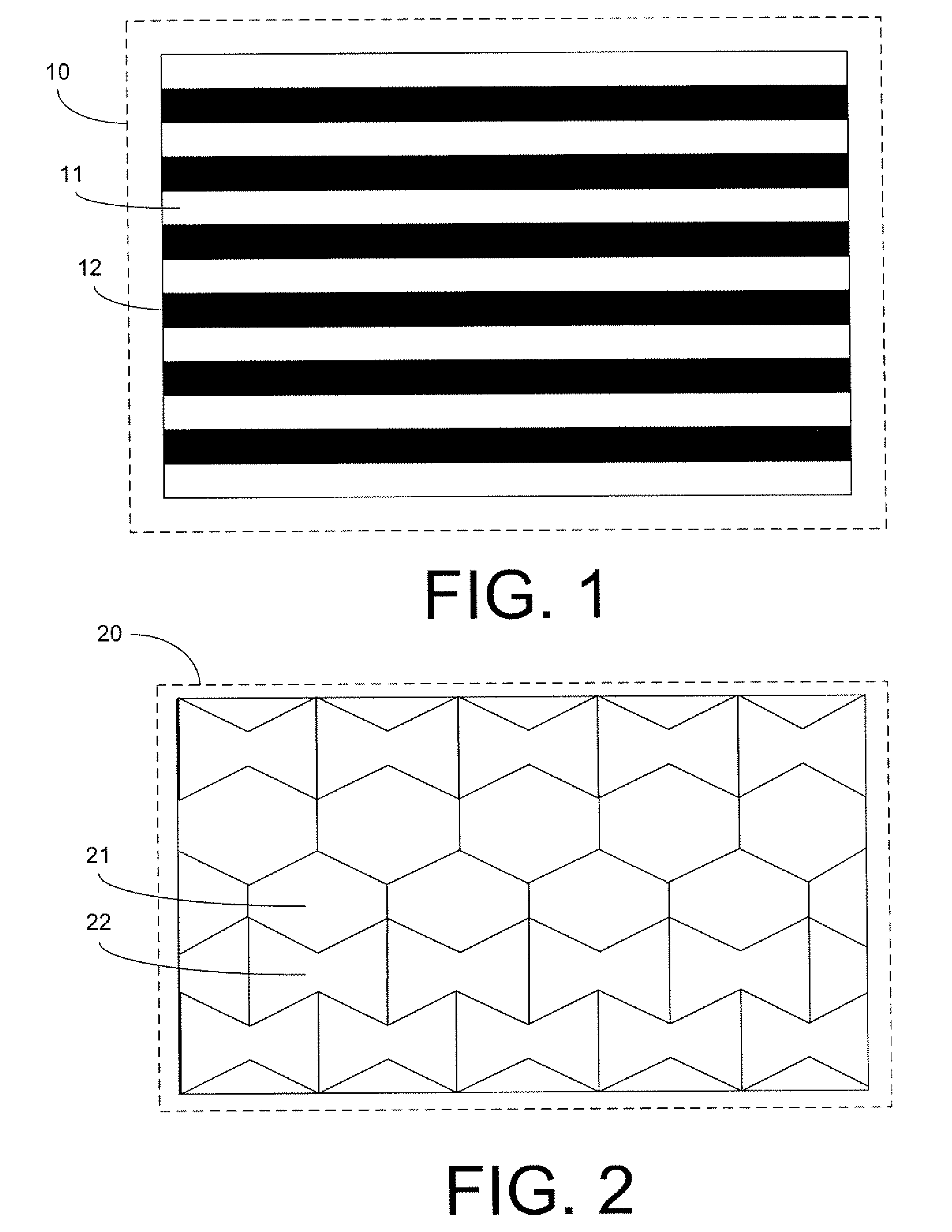
[0013]Referring now to the drawings, in which like numerals indicate like elements throughout the separate views, FIG. 1 shows a cross-sectional view of a composite material 10 of a particular embodiment of the present application. Composite materials are materials that result when two or more distinct materials, each having its own, usually different, characteristics, are combined. The combination may provide a composite with useful properties for specific applications. For example, composites may be useful in applications where thermal expansion is to be controlled. Thermal expansion is the dimensional change exhibited by a material as the temperature of the material changes.

[0014]The composite material 10 includes a first material 11 and a second material 12. The first material 11 has a positive coefficient of thermal expansion. A coefficient of thermal expansion is the fractional change in length or volume of a material per degree of temperature change. A material having a posit...


PUM

PropertyMeasurementUnit
coefficient of thermal expansionaaaaaaaaaa
thermal expansionaaaaaaaaaa
frictionaaaaaaaaaa

Abstract

A composite material for use in turbine support structures. The composite material may include a first material having a positive coefficient of thermal expansion and a second material having a negative coefficient of thermal expansion, a negative Poisson ratio, or both a negative coefficient of thermal expansion and a negative Poisson ratio.

Description

TECHNICAL FIELD[0001]The present application relates to composite materials and more particularly relates to a composite material having controlled thermal expansion for use in turbine support structures.BACKGROUND OF THE INVENTION[0002]The clearance between a turbine blade and the turbine housing, known as the tip clearance, is critical to the performance of a turbine. Tip clearances that are too large result in leakages that are detrimental to turbine performance. Tip clearances that are too small may result in friction or wear within a turbine and may cause turbine malfunction. Maintenance of tip clearances at a suitable level is important for efficient and robust operation of steam turbines and gas turbines.[0003]An important factor affecting tip clearances is the thermal expansions of the support structures of turbines. The outer shell of a turbine generally is supported by a structure separate from that supporting the turbine rotor. The outer shell of turbines often have exten...

Claims


Application Information

Patent Timeline
Patent Type & Authority Patents(United States)
IPC IPC(8): B32B7/02B32B9/00
CPCF01D25/28F02C7/28F05D2300/2102Y10T428/24992F05D2300/603F05D2300/614Y10T428/24942F05D2300/50212
Inventor NAMBURI, ADI NARAYANARAO, HAYAGREEVATHIAGARAJAN, CHINNIAH
Owner GENERAL ELECTRIC CO
Why Eureka
Try Eureka