Electronic component mounting method and electronic component mounting apparatus

a technology for electronic components and mounting methods, applied in metal working apparatuses, metal-working machine components, manufacturing tools, etc., can solve problems such as unstable pickup rate and increased pickup ra

Active Publication Date: 2009-05-19
YAMAHA MOTOR CO LTD
View PDF15 Cites 10 Cited by
  • Summary
  • Abstract
  • Description
  • Claims
  • Application Information

AI Technical Summary

Problems solved by technology

However, there has been a problem that a pickup rate is unstable for disturbance when the information about the pickup position shift obtained by the recognition process is less repeatable even once the pickup rate becomes stable, while the pickup rate increases if the information has repeatability.

Method used


Image

  • Electronic component mounting method and electronic component mounting apparatus
  • Electronic component mounting method and electronic component mounting apparatus
  • Electronic component mounting method and electronic component mounting apparatus

Examples


second embodiment

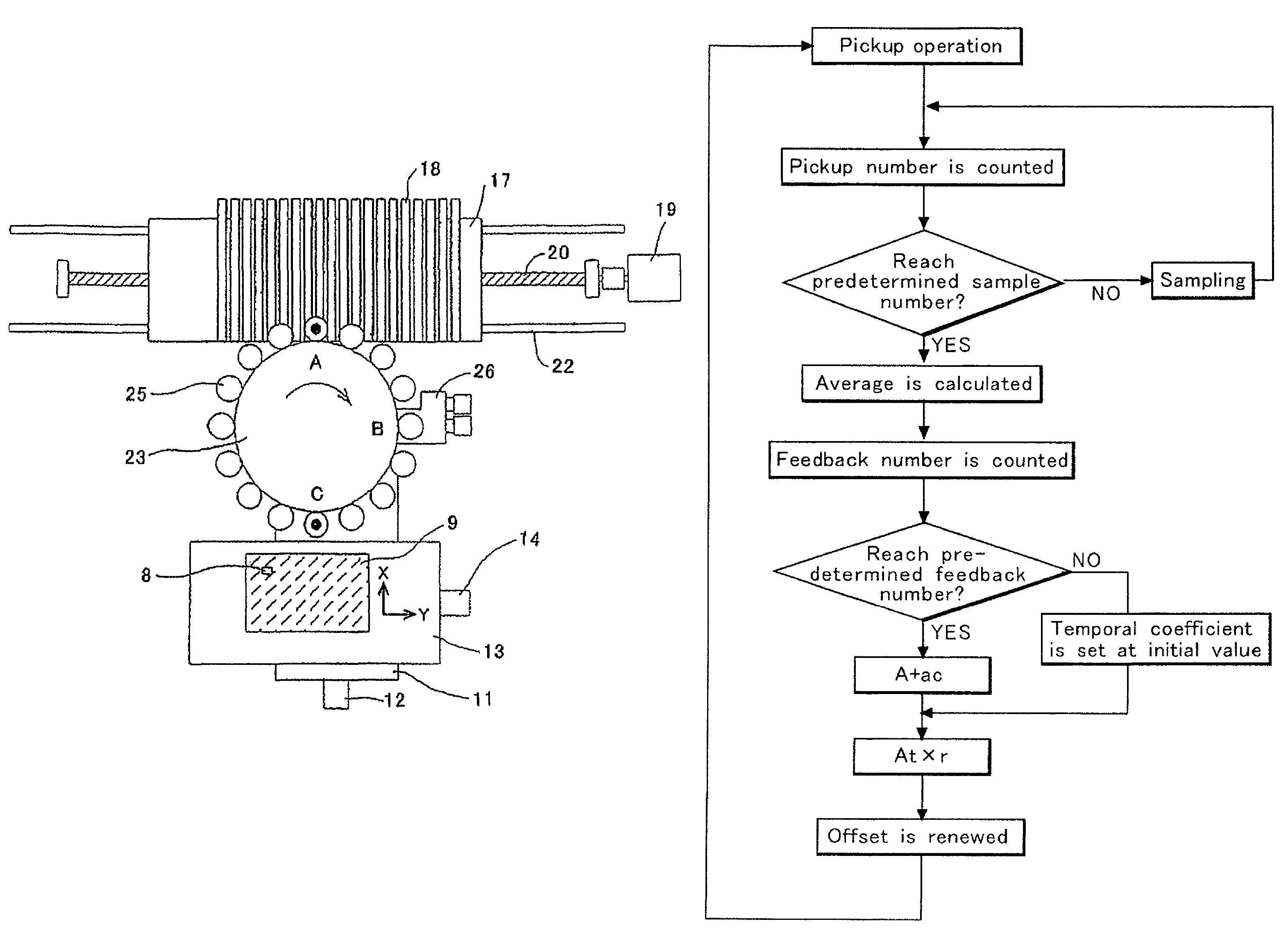
[0041]Next, a control for stabilizing the pickup operation of a second embodiment will be described based on a flowchart of FIG. 5. First, when the pickup operation in which the suction nozzle 24 picks up the electronic component 8 from the component feeding unit 18 is performed, a second counter (not shown) for counting a pickup number is incremented by 1. Then, the CPU 40 determines whether or not the count number reaches a predetermined sample number Sm. When the CPU 40 determines that the count number does not reach the predetermined sample number Sm, a sampling operation is performed. The image of the electronic component 8 taken by the component recognition camera 15 as described above is recognized by the recognition processing device 43, and when the positional shift of the electronic component 8 on the suction nozzle 24 is recognized, the positional shifting amount is stored in the RAM 41.

[0042]Then, the electronic component 8 is sequentially picked up from the component fe...

third embodiment

[0048]Next, a control for stabilizing the pickup operation of a third embodiment will be described based on a flowchart of FIG. 6. First, when the pickup operation in which the suction nozzle 24 picks up the electronic component 8 from the component feeding unit 18 is performed, a fourth counter (not shown) for counting a pickup number is incremented by 1. Then, the CPU 40 determines whether or not a pickup error occurs although the pickup operation is performed.

[0049]When the CPU 40 determines that no pickup error occurs, the CPU 40 determines whether or not the pickup count number reaches a predetermined sample number Sm. When the CPU 40 determines that the pickup count number does not reach the sample number Sm, a sampling operation is performed and the next pickup operation is performed. However, when the CPU 40 determines that the pickup error occurs, a fifth counter (not shown) for counting a pickup error number is incremented by 1 and calculates a pickup rate R=(1−e / c) based ...


PUM

PropertyMeasurementUnit
outer circumferenceaaaaaaaaaa
suctionaaaaaaaaaa
angleaaaaaaaaaa

Abstract

The invention is directed to increased stabilization of a pickup operation by reducing a reaction against disturbance by reducing a feedback value when a pickup rate is improved. A positional shifting amount of an electronic component on a suction nozzle before the electronic component is mounted on a printed board is stored in a RAM each time the component is picked up at a component feeding unit until a pickup count number reaches a predetermined pickup number, and a CPU calculates an average of the positional shifting amounts. When the pickup count number reaches the predetermined pickup number, the CPU obtains a temporary coefficient by adding an initial value to a value obtained by multiplying a negative coefficient by the pickup count number, and calculates a feedback value by multiplying the temporary coefficient by the average. The calculated feedback value is added to an offset value of a component pickup position to modify the offset value, and uses the offset value in the next pickup operation at the component feeding unit.

Description

CROSS-REFERENCE OF THE INVENTION[0001]This invention is based on Japanese Patent Application No. 2004-131300, the content of which is incorporated by reference in its entirety.BACKGROUND OF THE INVENTION[0002]1. Field of the Invention[0003]The invention relates to an electronic component mounting method and an electronic component mounting apparatus in which an electronic component is picked up by suction from any one of a plurality of component feeding units by a suction nozzle based on a offset value of a component pickup position, and the electronic component held by suction by the suction nozzle is recognized by a recognition processing device using an image taken by a component recognition camera, and mounted on a printed board.[0004]2. Description of the Related Art[0005]The pickup operation has been performed by using information about a pickup position shift in each of the component feeding units. That is, an image of the electronic component held by suction by the suction n...

Claims


Application Information

Patent Timeline
Patent Type & Authority Patents(United States)
IPC IPC(8): H05K3/30H05K13/04
CPCH05K13/0413Y10T29/53091Y10T29/4913Y10T29/53191Y10T29/53178Y10T29/49131Y10T29/49133H05K13/0417H05K13/08H05K13/04
Inventor KANO, YOSHINORITOMIFUKU, TAKESHIOKAMOTO, YOSHINORIUSUI, YOSHINAOTAKEMURA, IKUO
Owner YAMAHA MOTOR CO LTD
Why Eureka
Try Eureka