
Liquid crystal display device

a liquid crystal display and liquid crystal technology, applied in static indicating devices, non-linear optics, instruments, etc., can solve the problems of serious deterioration of liquid crystals, and deterioration of image quality of 1-dot inversion methods, so as to prevent deterioration of image quality

Active Publication Date: 2006-06-29
LG DISPLAY CO LTD
View PDF12 Cites 39 Cited by
  • Summary
  • Abstract
  • Description
  • Claims
  • Application Information

AI Technical Summary

Benefits of technology

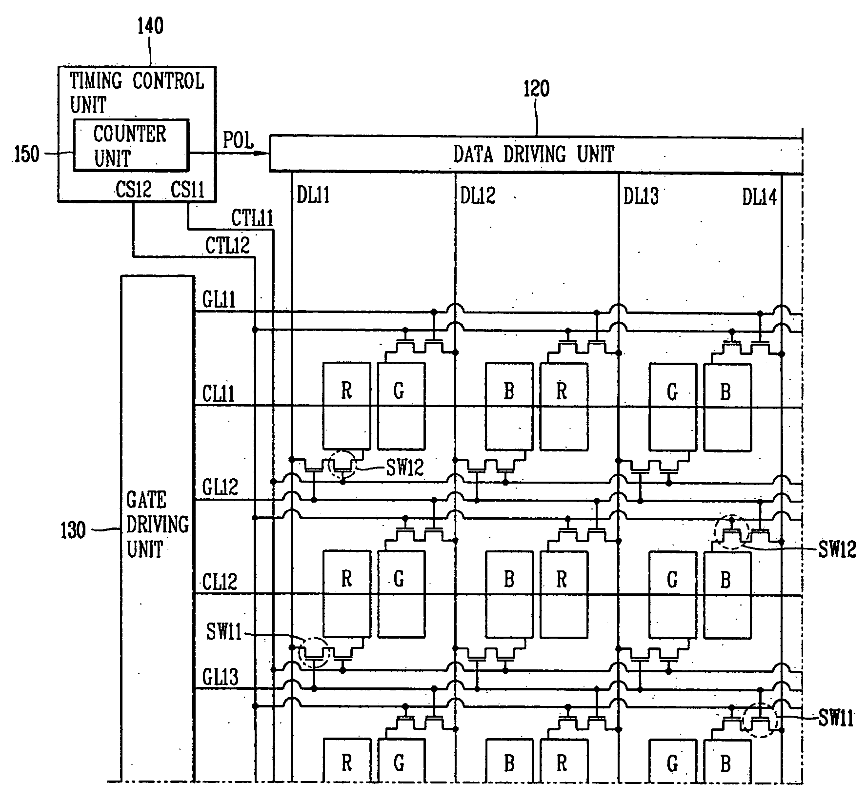
The present invention provides an LCD device that uses a 2-dot inversion method to prevent image quality degradation, while reducing the number of data lines and fabrication costs. The device includes a timing control unit, a plurality of gate lines, a plurality of data lines, and a data driving unit. The timing control unit generates control signals and a polarity signal based on the number of wave forms of the control signals. The data driving unit determines polarities of image data and supplies the data to the pixels in the first and second columns through the corresponding data lines. The technical effects of the invention include improved image quality and reduced fabrication costs.

Problems solved by technology

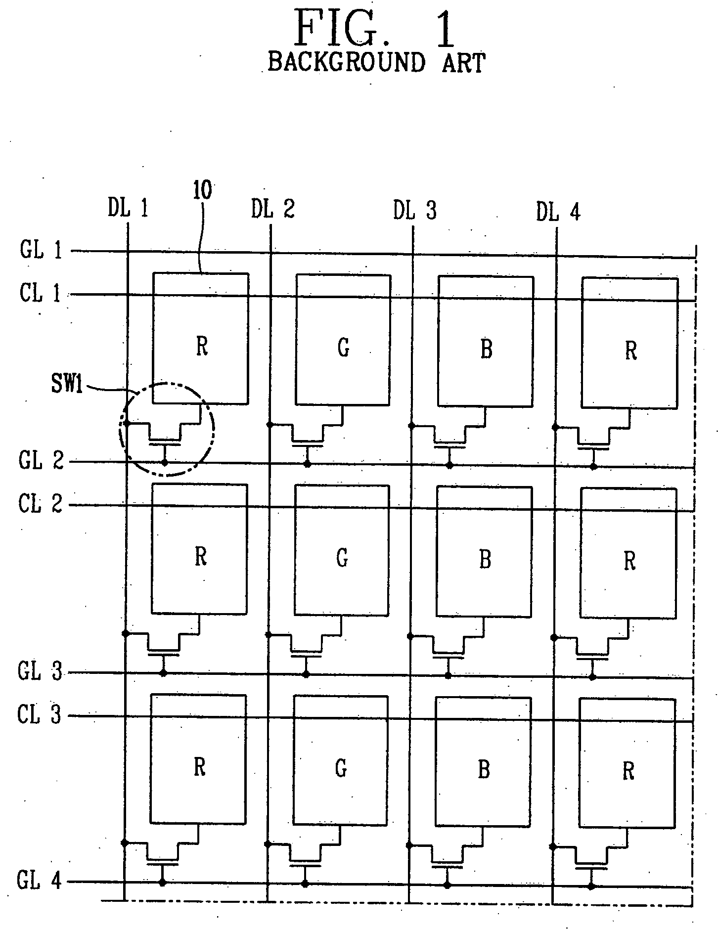
When a certain electric field is continuously applied to a liquid crystal layer of the LCD device, liquid crystals are deteriorated and undesirable after-images are generated by a DC voltage component.
However, the 1-dot inversion method still experiences some deterioration in image quality, such as deterioration due to crosstalk.
In particular, serious deterioration in image quality can be caused in an image where a specific pattern repetitively appears, as shown in FIG. 2A or FIG. 2B.
This increases fabrication costs.

Method used


Image

  • Liquid crystal display device
  • Liquid crystal display device
  • Liquid crystal display device

Examples


Embodiment Construction

[0035] Reference will now be made in detail to the preferred embodiments of the present invention, examples of which are illustrated in the accompanying drawings.

[0036] An LCD device to obtain the objects of the present invention includes: a timing control unit for generating a first control signal and a second control signal which are transitioned every ½ frame, and setting a polarity signal according to the count number obtained by counting the number of rising edges or falling edges of the first and second control signals; a plurality of gate lines arranged on a substrate in a horizontal direction; a plurality of data lines arranged on the substrate in a longitudinal direction and crossing the gate lines; a plurality of pixels arranged in a matrix format on the substrate, two of the pixels being provided at every region divided by the gate lines and the data lines; and a data driving unit for determining polarities of first image data and second image data according to the polar...


PUM


Abstract

A liquid crystal display device includes a timing control unit for generating first and second control signals, which are transitioned every ½ frame. A polarity signal is set according to a count number obtained by counting the number of wave forms of the first and / or second control signals. A plurality of gate lines and data lines are arranged on a substrate crossing each other. A plurality of pixels are arranged in a matrix format on the substrate, with two pixels being provided in the regions divided by the gate and data lines. A data driving unit determines polarities of the first and second image data according to the polarity signal being received from the timing control unit, and then supplies the first and second image data to the pixels in the first and second columns through the first and second data lines, respectively.

Description

[0001] This application claims the benefit of the Korean Application No. 10-2004-0115626 filed on Dec. 29, 2004, which is hereby incorporated by reference. BACKGROUND OF THE INVENTION [0002] 1. Field of the Invention [0003] The present invention relates to an LCD device, and more particularly, to an LCD device which is driven with a small number of data lines in comparison with the background art. The present invention also relates to a 2-dot inversion method of driving an LCD device, thereby preventing deterioration in image quality caused by a specific pattern. [0004] 2. Description of the Background Art [0005] Display devices as visual information transfer media have gained more importance in an information oriented society. Among them, liquid crystal display (LCD) devices have rapidly replaced traditional cathode ray tubes (CRT) devices as the next-generation of display devices because superior legibility, low power consumption and high definition. [0006] An LCD device includes ...

Claims


Application Information

Patent Timeline
Patent Type & Authority Applications(United States)
IPC IPC(8): G09G3/36
CPCG09G3/3614G09G3/3648G09G2300/0426G09G2300/0443G09G2300/0823G09G2310/06G02F1/133
Inventor PARK, JOON-KYU
Owner LG DISPLAY CO LTD
Learn More