Conveying device

a technology of conveying device and guide rod, which is applied in the direction of charging, lighting and heating apparatus, furniture, etc., can solve problems such as affecting the quality of guidan

Inactive Publication Date: 2010-12-14
MASCHFAB MULLER WEINGARTEN AG
View PDF7 Cites 3 Cited by
  • Summary
  • Abstract
  • Description
  • Claims
  • Application Information

AI Technical Summary

Benefits of technology

[0006]The object underlying the invention is to further develop the prior art and suggest a guide for the extension arm(s) of a telescoping feeder, which guide assures good quality of guidance.
[0010]Rapid accelerations and speeds are necessary for attaining lower conveying times. The dynamic movements are easy to control because the suggested guide system is characterized by great stiffness. Thus only minor vibrations occur when the workpiece is conveyed, which promotes defined placement onto the die, and also the holding forces during conveying are easy to control.
[0012]It is also possible to use two drives in an advantageous manner, this enhancing the functional security of the conveying device, i.e. if one drive fails, the second drive would move the telescoping feeder out of a possible collision area.
[0015]It is also possible to have the transverse crossmember and thus the workpiece at an inclined position with no problem, since the vertical axes can be traveled independent of one another. Likewise, double parts can be conveyed with no limitation.

Problems solved by technology

However, problems occur in particular during use on large conveying paths.
However, since the length of the extension arm is supposed to be as short as possible for preventing edges during conveying and for preventing collisions during the shaping process, this also affects the quality of the guidance.

Method used


Image

  • Conveying device
  • Conveying device
  • Conveying device

Examples


Embodiment Construction

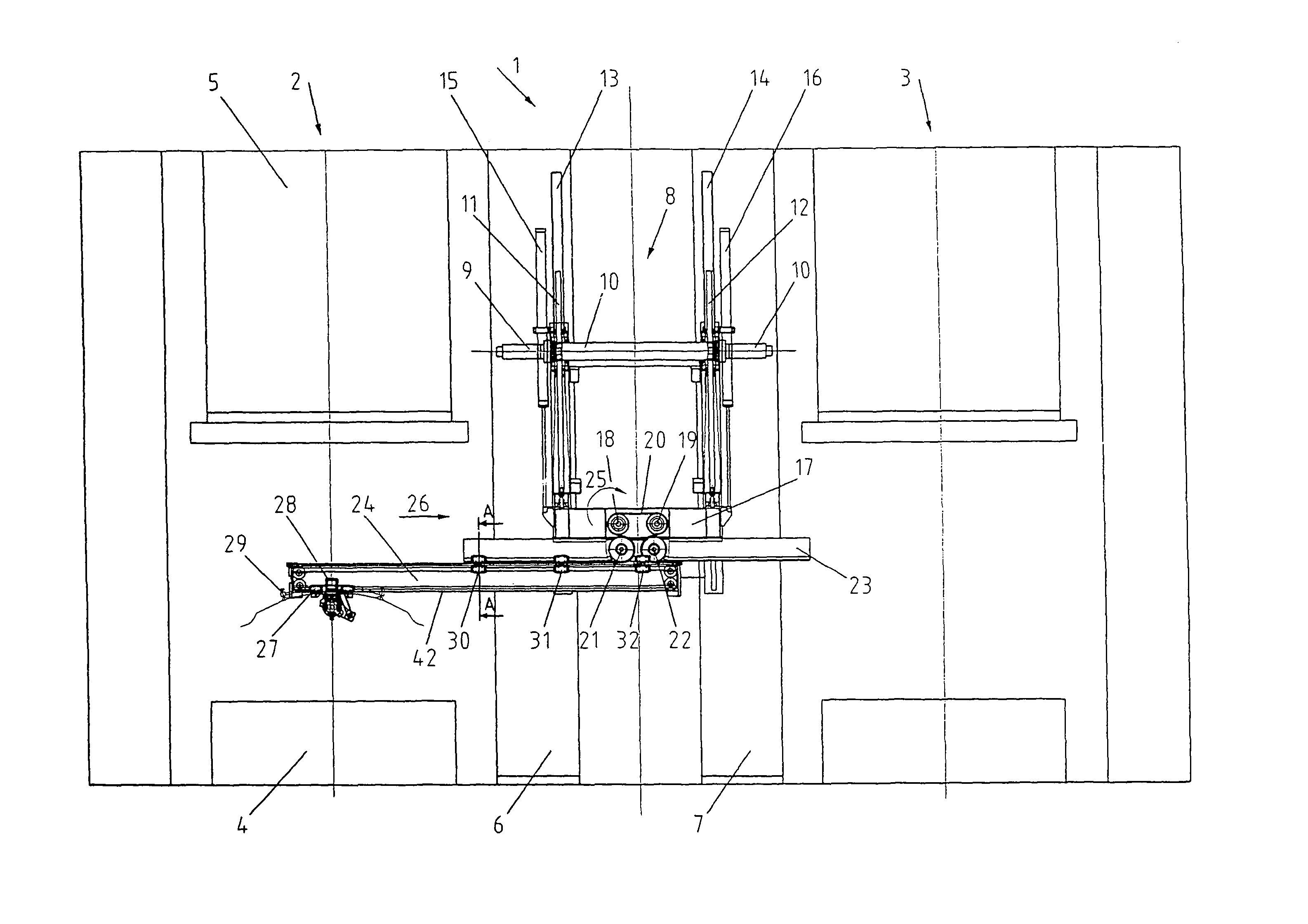
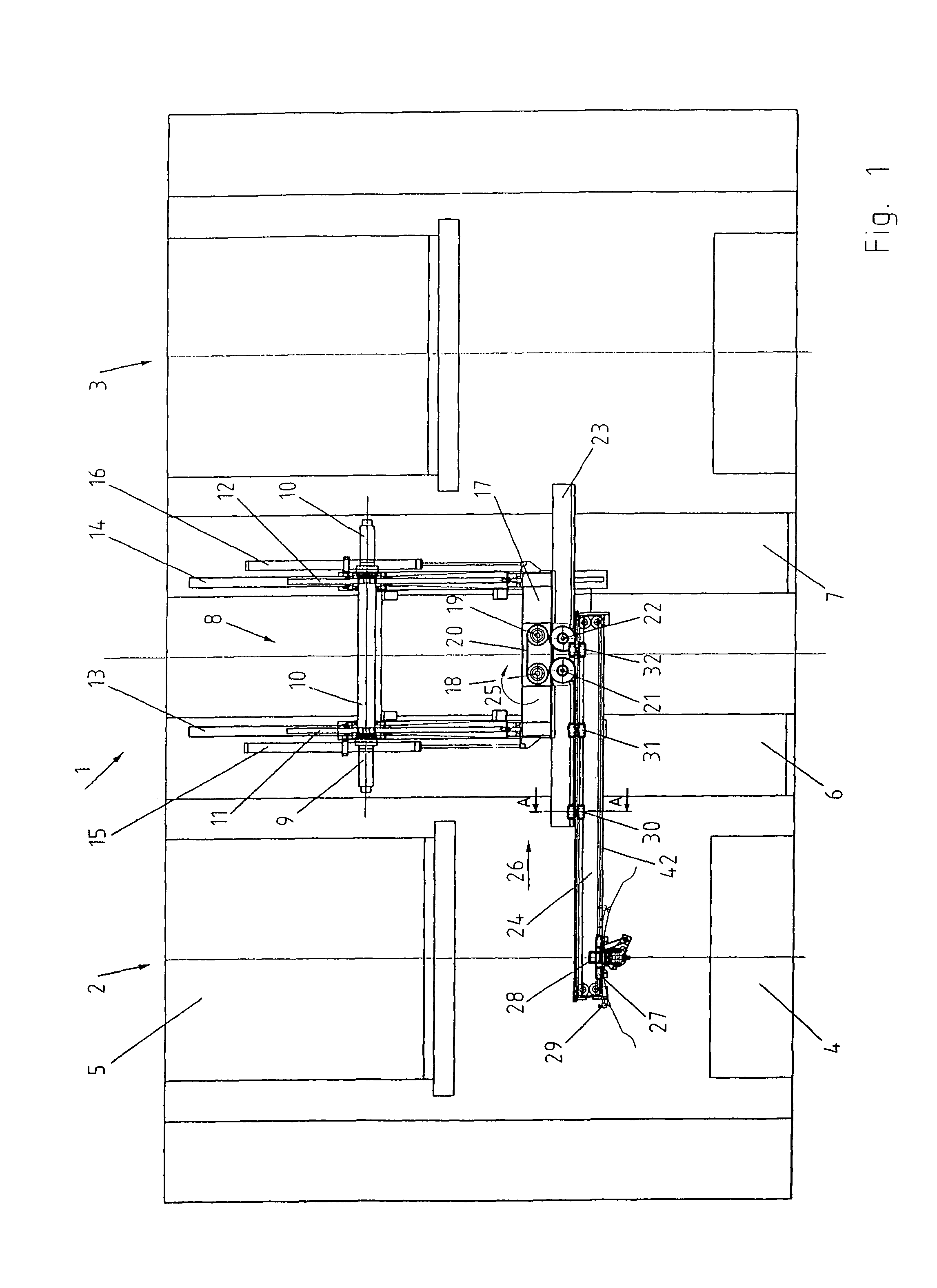
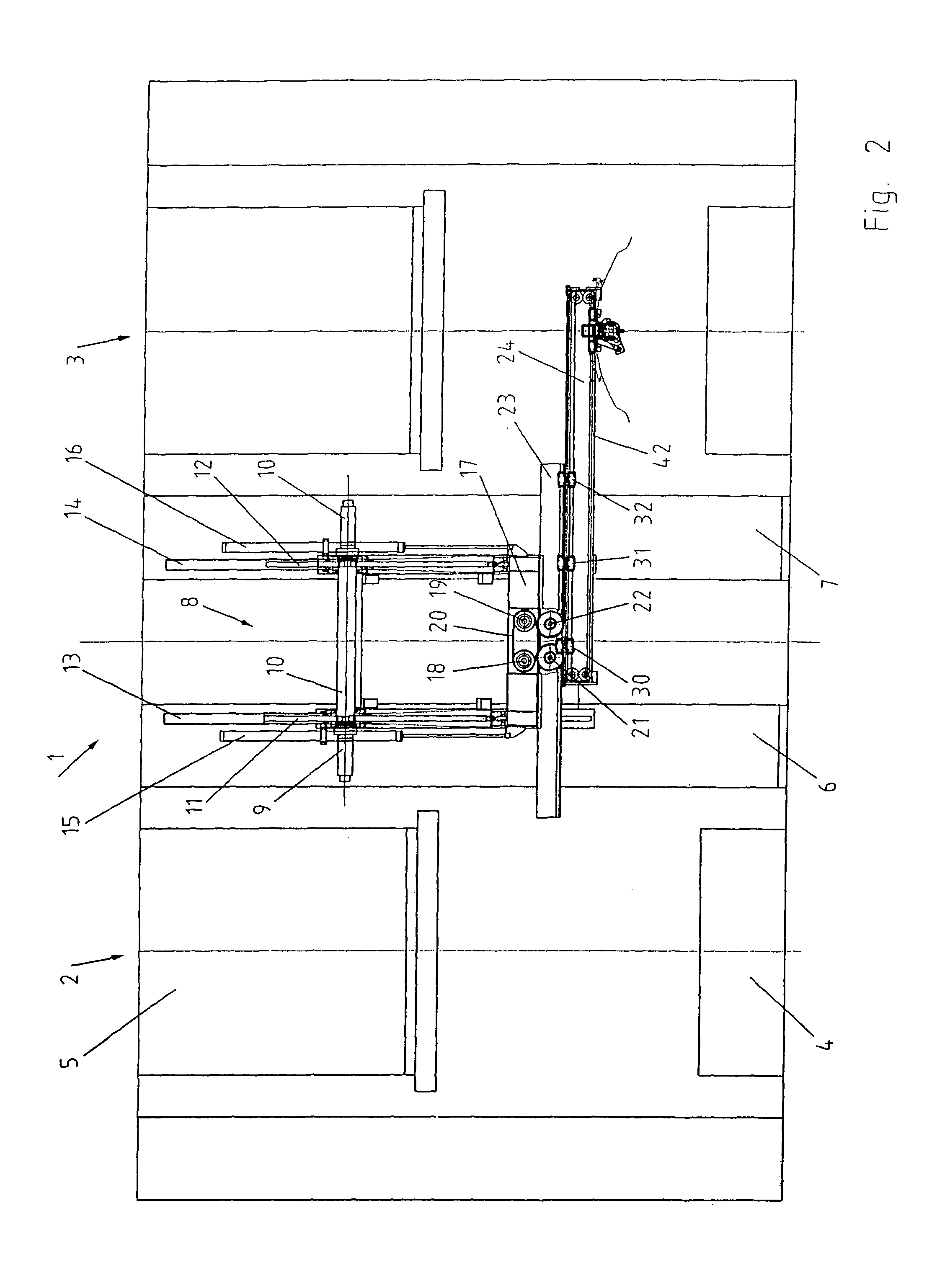
[0020]FIG. 1 depicts partial views of the shaping areas of the presses 2 and 3 in a simplified depiction of a press line 1. The sliding table 4 and the ram 5 can be seen. The punch and die are not shown in greater detail. The telescoping feeder 8 is attached to the press uprights 6, 7. Fixed, controllable motors 9, 10 effect the drive for the vertical movement and act via pinion gears on racks 11, 12. Linear guides 13, 14 assure certain vertical guidance. Forced synchronization of the lift movement is attained using the connecting shaft 41. For unloading the drives 9, 10, the masses to be moved can be compensated by cylinders 15, 16.

[0021]The racks 11, 12 are joined to the transverse crossmember 17 on which are arranged the motors 18, 19 that drive a toothed belt 20. For reasons of functional security, two motors are suggested 18, 19 so that if one of the motors fails the telescoping feeder can be moved out of a potential collision area using the second motor.

[0022]The toothed belt ...


PUM


Abstract

Disclosed is a device for conveying workpieces through a press working line or a transfer molding press. The conveying device is embodied as a telescopic feeder and is designed such that a jib which can be displaced in a longitudinal direction is mounted or guided by means of guiding carriages that travel along. An adequate entraining mechanism is provided in order to ensure the traveling motion of the guiding carriages.

Description

BACKGROUND OF THE INVENTION[0001]The invention relates to a conveying device for conveying workpieces through a press line, transfer press, or the like.[0002]Where the manufacture of a workpiece calls for a plurality of punch and shaping operations, then for economic production the necessary individual operations can be carried out in a press line, transfer press, or large component transfer press.[0003]As a rule, such systems are provided with conveying device for automatically conveying workpieces. These conveying device either possess their own drives or are actuated by the press drive. DE 198 01 731 A1 discloses a conveying device with discrete drives. Two stationary drive motors drive a telescoping extension arm arrangement via a traction means arrangement. By controlling the speed of rotation and direction of rotation of the drive motors, the conveying device known as a telescoping feeder performs horizontal and vertical movements. The required conveying path generally compris...

Claims


Application Information

Patent Timeline
Patent Type & Authority Patents(United States)
IPC IPC(8): B65G37/00B21D43/05B65G47/90
CPCB21D43/05B65G47/901
Inventor REICHENBACH, RAINER
Owner MASCHFAB MULLER WEINGARTEN AG
Why Eureka
Try Eureka