Foldable portable terminal device

a portable terminal and portable technology, applied in the field of foldable portable terminal devices, can solve the problems of increasing design restrictions, sound cannot be easily caught, and the design of components on the upper housing is restricted, so as to easily catch the sound output, and reduce the thickness of the main body

Inactive Publication Date: 2010-12-21
PANASONIC CORP
View PDF10 Cites 5 Cited by
  • Summary
  • Abstract
  • Description
  • Claims
  • Application Information

AI Technical Summary

Benefits of technology

[0010]With this configuration, the foldable portable terminal device having a single axis structure that is foldable or rotatable is configured to secure a space for sound outputted from the speaker to be transmitted even in the folded state in which the speaker sound hole faces inside, thereby making the sound outputted from the speaker be easily caught.
[0024]Further, the sound outputted from the speaker can be easily caught regardless of the state of the housing, because it is possible to secure the space for sound outputted from the speaker to be transmitted even in the state in which the speaker sound hole faces inside. In addition, because it is not necessary to install any more speakers or speaker sound holes, a foldable portable terminal device that guarantees flexibility in design may be provided.

Problems solved by technology

In this case, if the speaker sound hole is provided on a surface facing away from the display unit of the first housing as in the case of a conventional foldable portable telephone, there is a problem that the sound cannot be caught easily, because the speaker sound hole faces inside when the portable telephone is folded with the display unit facing outside.
Further, while utilizing the opening disclosed in the above Japanese Patent Unexamined Publication No. 2003-60757 may solve the above problem, however, this also increases design restrictions for components on an upper housing and a design, because it is necessary to provide an opening for the first housing, which requiring reduction of an area of the display unit and substrate in the first housing.

Method used


Image

  • Foldable portable terminal device
  • Foldable portable terminal device
  • Foldable portable terminal device

Examples


first embodiment

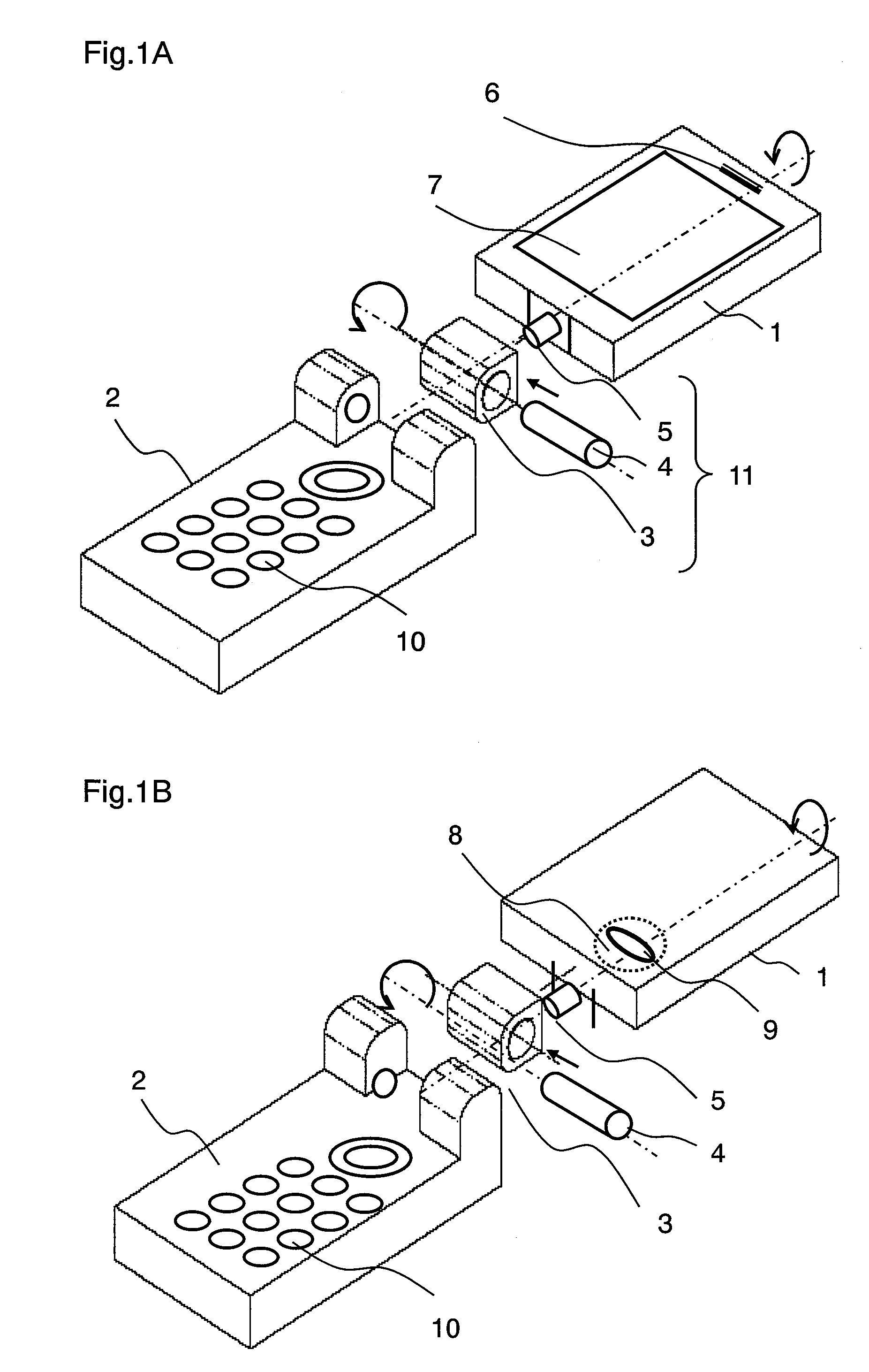
[0064]An invention according to a first embodiment of the present invention is now described. FIG. 1A and FIG. 1B show exploded perspective views of a housing structure of a rotatably foldable portable terminal device according to the first embodiment of the present invention.

[0065]In FIG. 1A and FIG. 1B, first housing 1 and second housing 2 are foldably and rotatably coupled via coupling unit 3. Hinge unit 11 includes coupling unit 3 that couples first housing 1 and second housing 2, and two shafts of first rotary shaft 4 that performs a folding / unfolding action and second rotary shaft 5 that performs rotary action in a direction perpendicular to a folding / unfolding direction. First housing 1 may perform the folding / unfolding action and the rotary action. FIG. 1A shows an unfolded state in which first housing 1 and second housing 2 are opened by the folding / unfolding action of a first rotary shaft 4. FIG. 1B shows a state in which, after being opened by the folding / unfolding action...

second embodiment

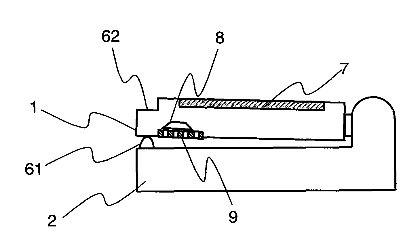
[0072]An invention according to a second embodiment of the present invention is described. FIG. 4A and FIG. 4B show external views of a rotatably foldable portable terminal device according to the second embodiment of the present invention. Further, FIG. 5 shows a sectional view of the rotatably foldable portable terminal device according to the second embodiment of the present invention. In FIG. 4A, FIG. 4B, and FIG. 5, the same components as in FIG. 1 are indicated by the same reference numerals and explanation for such components are omitted.

[0073]FIG. 4A shows the closed state in which display unit 7 of first housing 1 faces inside, and FIG. 4B shows the folded state in which first housing 1 is rotated by 180 degrees in a rotary direction from the unfolded state, and then first housing 1 is overlaid on second housing 2 with display unit 7 exposed outside. FIG. 5 shows a sectional view, taken at line 5-5 in FIG. 4B, of the folded state in which first housing 1 is rotated by 180 d...

third embodiment

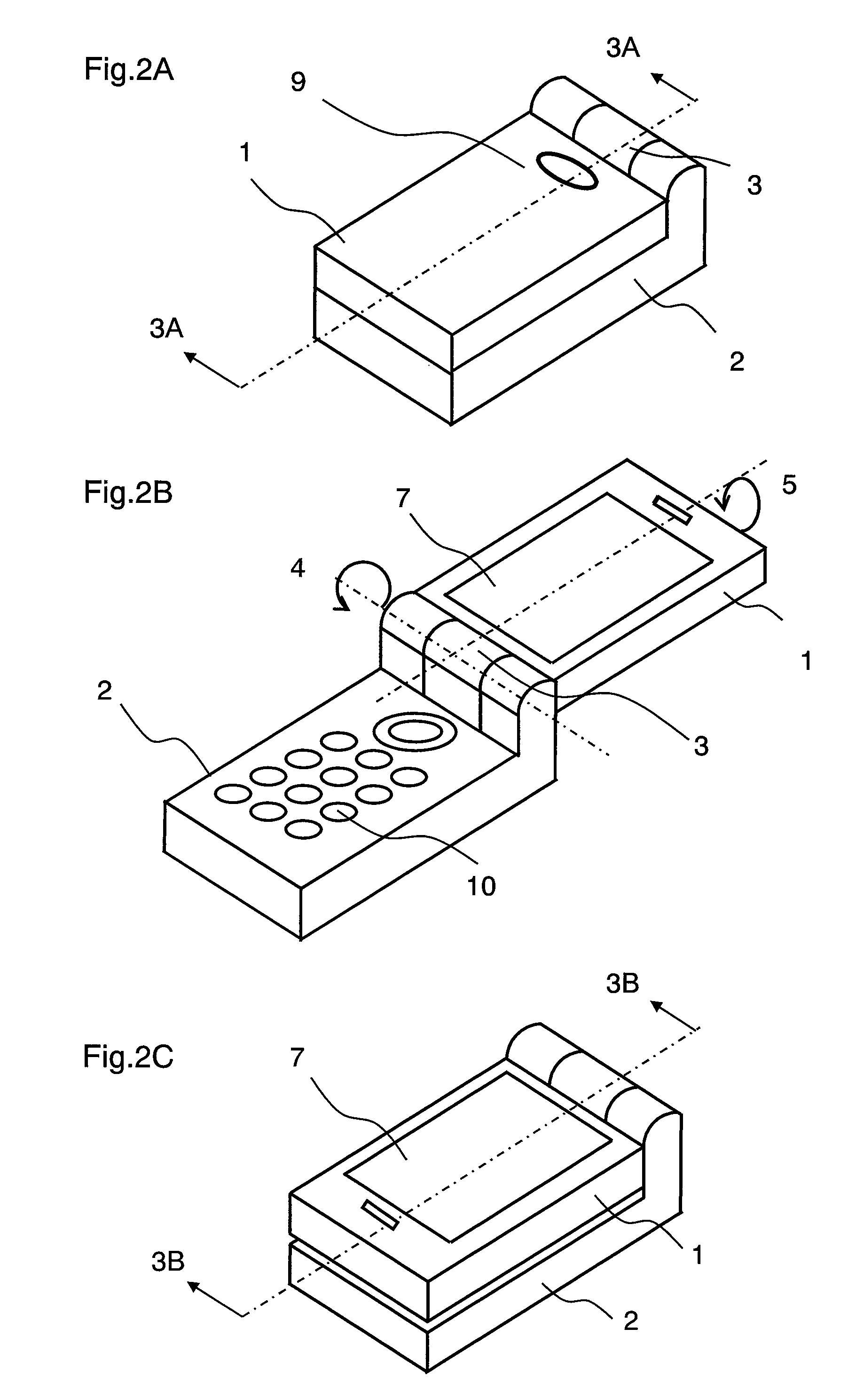
[0076]FIG. 6A and FIG. 6B show external views of a rotatably foldable portable terminal device according to a third embodiment of the present invention. Further, FIG. 7A and FIG. 7B show sectional views of the rotatably foldable portable terminal device according to the third embodiment of the present invention. In FIG. 6A, FIG. 6B, FIG. 7A, and FIG. 7B, the same components as in FIG. 1 are indicated by the same reference numerals and explanation for such components are omitted here.

[0077]FIG. 6A shows the unfolded state in which display unit 7 of first housing 1 faces inside, and FIG. 6B shows the folded state in which first housing 1 is rotated by 180 degrees in a rotary direction from the open state, and then first housing 1 is overlaid on second housing 2 with display unit 7 exposed outside. FIG. 7A shows a sectional view, taken at line 7A-7A in FIG. 6A, of the closed state in which display unit 7 of first housing 1 faces inside, and FIG. 7B shows a sectional view, taken at line...


PUM


Abstract

A foldable portable terminal device provided with a first housing includes a display unit, a speaker and a speaker sound hole, a second housing, and a hinge unit that couples the housings rotatably around two directions that perpendicularly intersect with each other. The device is configured such that coupling of the first housing and the hinge unit is coupled to a second rotary shaft of the hinge unit at a position closer to a surface having the speaker sound hole than a midpoint in a cross-section in a thickness direction of the first housing, and that a gap formed in a folded state in which the first housing is overlaid on the second housing with a surface having the speaker sound hole facing inside is greater than a gap formed in the folded state with the surface having the speaker sound hole facing outside.

Description

[0001]THIS APPLICATION IS A U.S. NATIONAL PHASE APPLICATION OF PCT INTERNATIONAL APPLICATION PCT / JP2005 / 023335.TECHNICAL FIELD[0002]The present invention relates to a foldable portable terminal device having a speaker, and in particular, to a portable terminal device allowing a clear output of sound from a speaker in a state in which one housing is overlaid on another housing.BACKGROUND ART[0003]Conventional foldable portable terminal devices that are typically used are reduced in size and weight by designs such as an internal component arrangement and a housing structure. Among such foldable portable terminal devices, a foldable portable telephone, for example, includes a first housing provided with a display unit, an receiver, an antenna, and so on, and a second housing provided with an operating unit having a main operational function, a microphone, and so on.[0004]As shown in FIG. 12A and FIG. 12B, a foldable portable terminal device is known which is configured such that speake...

Claims


Application Information

Patent Timeline
Patent Type & Authority Patents(United States)
IPC IPC(8): H04M1/00H04B1/08
CPCH04M1/021H04M1/03
Inventor YOKOTA, MASANORINANMOKU, TERUOHASEGAWA, AKIRA
Owner PANASONIC CORP
Why Eureka
Try Eureka