Rotatively operating tool for rotatively operated member having a pair of engaging surfaces

a technology of rotating operating tools and rotating parts, which is applied in the direction of wrenches, screwdrivers, manufacturing tools, etc., can solve the problems of increasing the number of parts, unsuitable wrenches for long-time operation, and complicated operation, and achieve reliable lever turning movement

Inactive Publication Date: 2006-10-03
HONDA MOTOR CO LTD
View PDF14 Cites 3 Cited by
  • Summary
  • Abstract
  • Description
  • Claims
  • Application Information

AI Technical Summary

Benefits of technology

[0007]The present invention has been accomplished with such circumstances in view, and it is an object of the present invention to provide a rotatively operating tool having an extremely simple structure, wherein while ensuring that a rotatively operated member is rotated in one direction, the rotatively operated member can be also rotated in an opposite direction, as required, by the reciprocally turning operation of the tool.
[0012]In this way, with the rotatively operating tool having the first feature of the present invention, the rotatively operated member, while being able to be rotated in one direction, can be also rotated in the opposite direction, as required, by the reciprocally turning operation of the tool. With the tool, the lever need only be turnably connected to the handle and hence, the tool has an extremely simple stricture and can be produced at low cost.
[0014]With the second feature, when no force is applied to the lever, the lever is held in a given position relative to the handle. Therefore, the head provided at the tip end of the lever can be easily caught on the operated portion of the rotatively operated member, and when the operator has released his hand from the lever grasped along with the handle by the operator, the lever is returned to a predetermined position, and the lower jaw provided at the tip end of the handle is automatically disengaged from the engaging surface of the operated portion. Therefore, the subsequent operation is easy.
[0016]With the third feature, even if there is a foreign matter existing in the vicinity of the operated portion of the rotatively operated member, the foreign matter is prevented from being put between the handle and the lever. Therefore, it is possible to achieve the reliable turning movement of the lever.

Problems solved by technology

This operation is troublesome and especially, the wrench is not suitable for a long-time operation.
However, such special tool can rotate the rotatively operated member only in one direction and for this reason, when the rotatively operated member is to be rotated in an opposite direction, it is necessary to recatch the tool with an opposite orientation each time.
In such a case, the operation is rather complicated with the tool for rotating the rotatively operated member only in one direction as described above.
However, the wrench described in Patent Document 1 has a problem that a means is required for detecting a state in which the handle has been pushed to the operated portion of the rotatively operated member, inevitably resulting in an increase in number of parts, an increase in cost and moreover, an increase in weight.

Method used


Image

  • Rotatively operating tool for rotatively operated member having a pair of engaging surfaces
  • Rotatively operating tool for rotatively operated member having a pair of engaging surfaces
  • Rotatively operating tool for rotatively operated member having a pair of engaging surfaces

Examples


Embodiment Construction

[0022]The mode for carrying out the present invention will now be described by way of an embodiment with reference to the accompanying drawings.

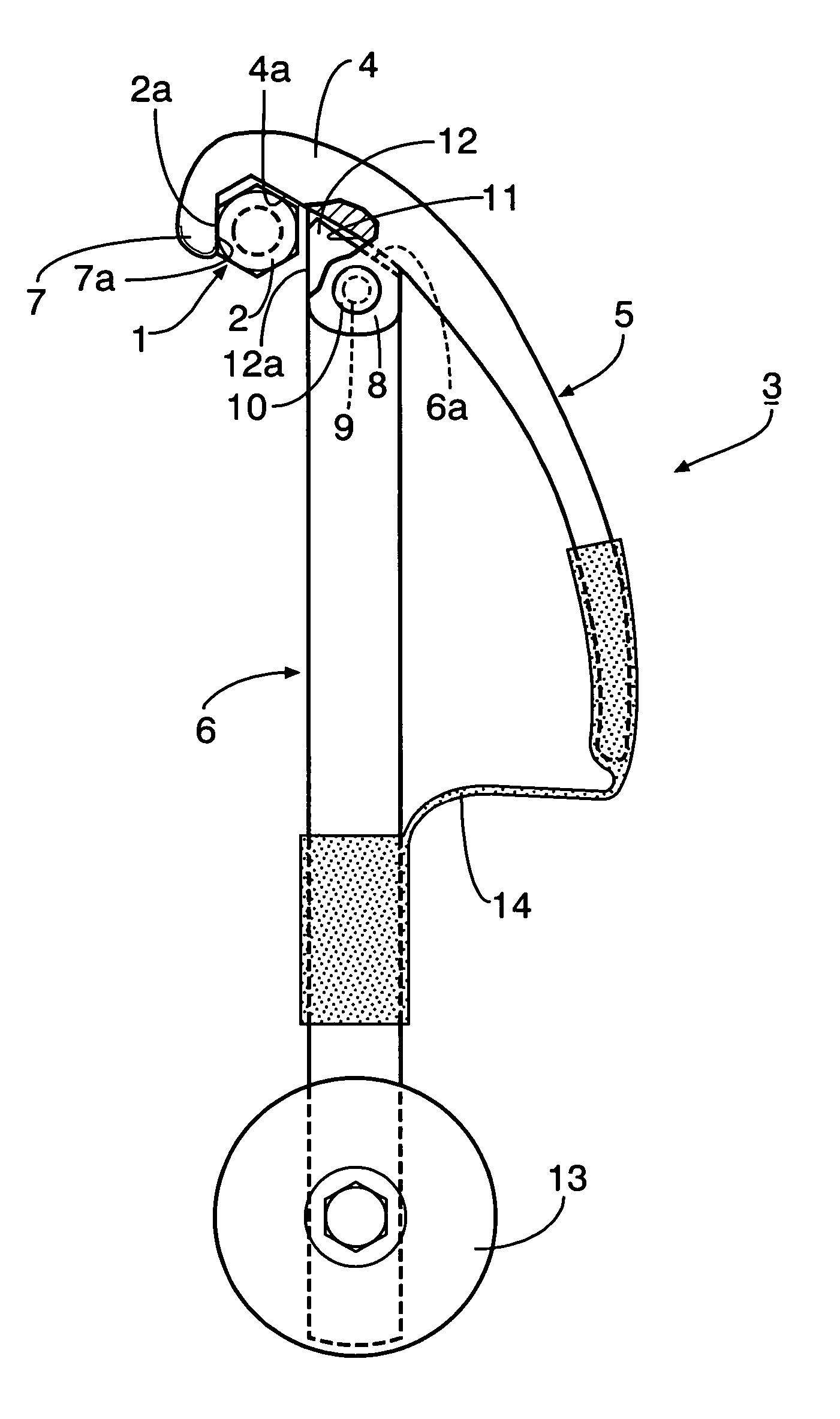
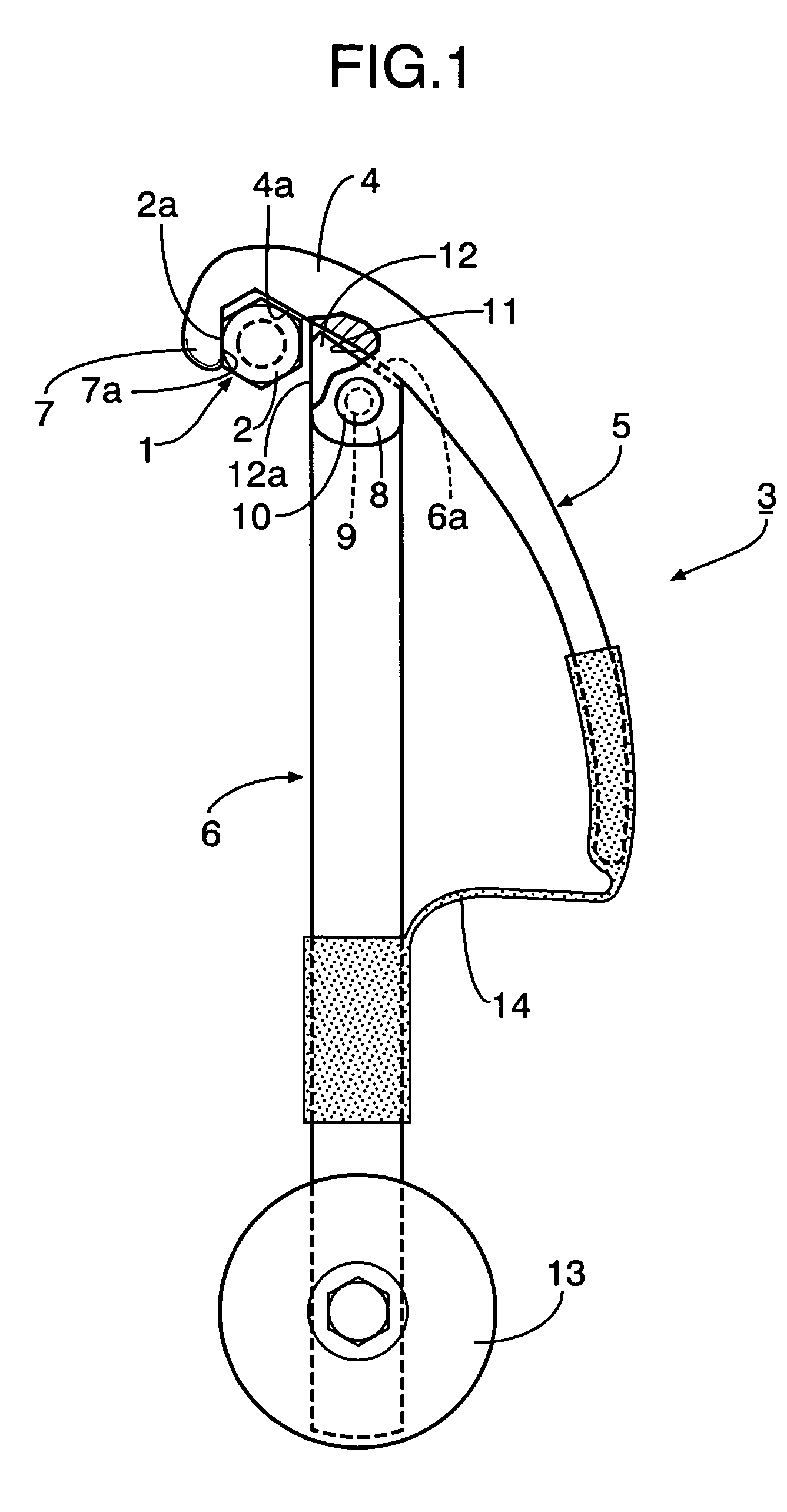
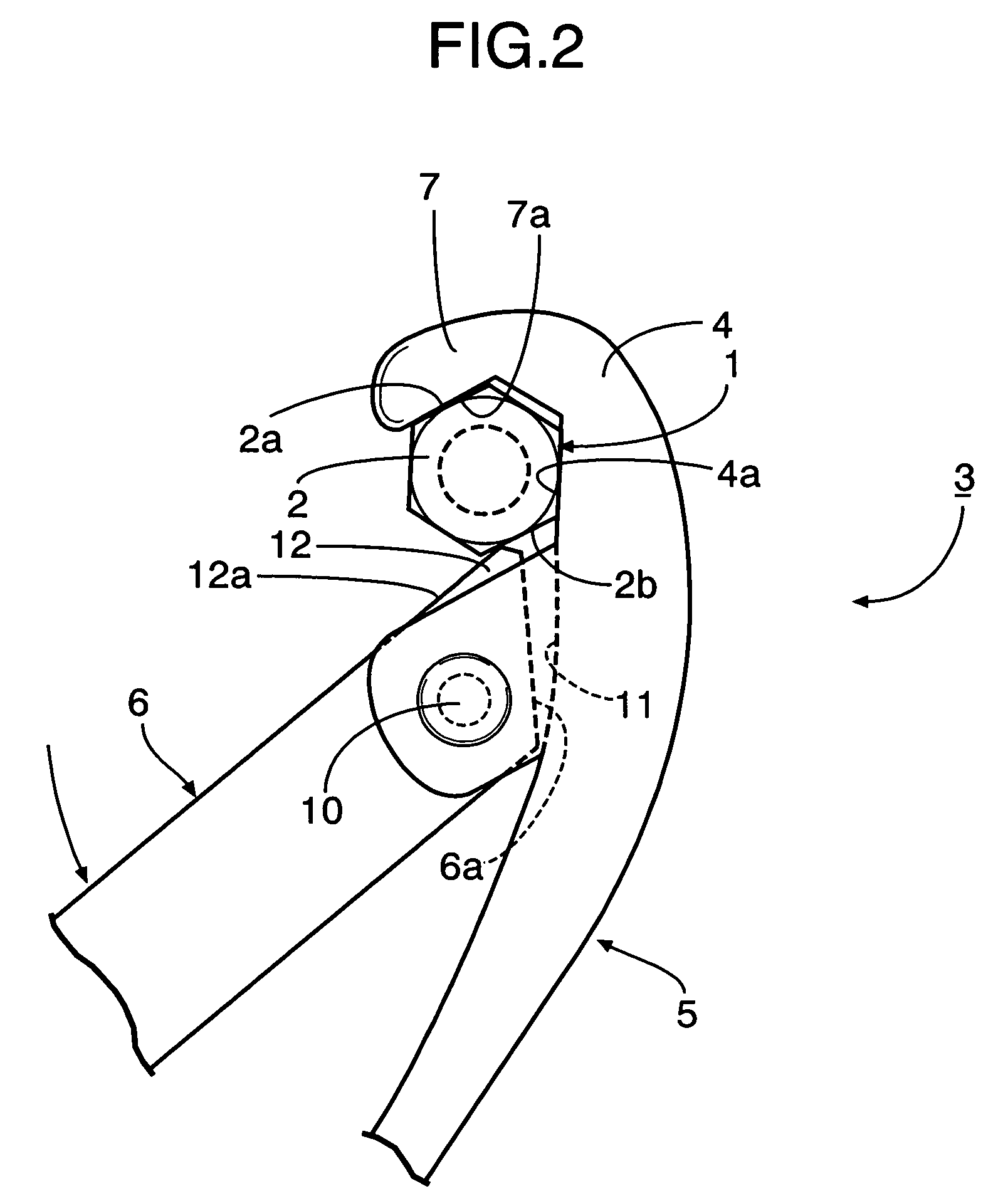
[0023]Referring first to FIG. 1, a bolt 1 which is one example of a rotatively operated member is provided with a bolt head 2 as an operated portion for rotation of the bolt 1. The bolt head 2 is of a substantially regular hexagonal shape and has three sets of engaging surfaces 2a and 2b forming pairs at distances of 180° in a circumferential direction. A rotatively operating tool 3 according to the present invention is intended to rotate a rotatively operated member such as the bolt 1 by rotatively operating an operated portion such as the bolt head 2.

[0024]The rotatively operating tool 3 includes a lever 5 having a head 4 integrally provided at its tip end, and a handle 6 grasped at its base end and turned by an operator. The head 4 of the lever 5 is of a hook-shape and has an upper jaw 7 formed at its tip end and having an inner surface 7...


PUM


Abstract

In a rotatively operating tool, a lever (5) having a head (4) at its tip end is turnably connected to a handle (6) provided at its tip end with a lower jaw (12). The head (4) is provided with an upper jaw (7) brought into engagement with an engaging surface (2a) of a bolt head (2). A spring (14) is mounted between the lever (5) and the handle (6) for biasing the lever (5) to turn it in a direction of abutment of a stopper face (11) of the lever (5) against the handle (6). When the handle (6) is turned in one direction, the lower jaw (12) at the tip end of the handle (6) is brought into abutment against an engaging surface (2b) of the bolt head (2), whereby the bolt head (2) is clamped between the lower jaw (12) and the upper jaw (7). When the handle (6) is turned in an opposite direction, it is brought into a state in which the clamping of the bolt head (2) is canceled. Even when the lever (5) is turned against a biasing force of the spring (14), the bolt head (2) is clamped between the upper jaw (7) and the lower jaw (12). Thus, it is possible to provide a rotatively operating tool having a simple structure, which is designed so that a rotatively operated member such as a bolt can be rotated in one direction and even in an opposite direction as required by the reciprocally turning operation of the tool.

Description

FIELD OF THE INVENTION[0001]The present invention relates to a rotatively operating tool for rotatively operating a rotatively operated member having an operated portion provided with engaging surfaces forming a pair at a distance of 180° in a circumferential direction at the operated portion, such as a hexagon headed bolt, a hexagon nut or a shaft hexagonal in section.BACKGROUND ART[0002]In general, a wrench is used for the rotative operation of a rotatively operated member having an operated portion as described above. In a case of a usual wrench, however, it is required that the wrench is once removed from the rotatively operated member every time the rotatively operated member is rotated over a certain angle and thereafter, the wrench be caught again on another engaging surface of the operated portion of the rotatively operated member. This operation is troublesome and especially, the wrench is not suitable for a long-time operation. Therefore, a special tool of a ratchet type i...

Claims


Application Information

Patent Timeline
Patent Type & Authority Patents(United States)
IPC IPC(8): B25B13/28B25B13/32B25B13/46
CPCB25B13/28B25B13/46
Inventor HASEGAWA, YOSHIHISA
Owner HONDA MOTOR CO LTD
Why Eureka
Try Eureka