Electro active elastic compression bandage

Inactive Publication Date: 2011-01-11
DANFOSS AS
View PDF192 Cites 46 Cited by
  • Summary
  • Abstract
  • Description
  • Claims
  • Application Information

AI Technical Summary

Benefits of technology

[0006]It is a task of this invention to supply an active support for a body extremity such as a leg, which can be used by a person underneath the clothes and will reduce mobility of the patient, so that the actuation elements build into the stocking may operate in a two-way communication, where stimulations are in response to the actual state of the stocking itself, the actuation elements working as sensors too. An alternative possibility is to stimulate in response to signals from some external sensor, perhaps registering the heart rate, the blood flow, body temperature, moist under the stocking due to sweat or other parameters. It is as an example possible to synchronise the actuation of the stocking with the heart rate in such a way that the stocking is relaxed during the systolic period to allow free flow in the arteries, while the contraction takes place during the diastolic period in order to stimulate peristaltic flow in the veins. This task is solved in that an elastic bandage comprises an elastic layer for surrounding a body extremity to exert compressive force on the extremity, where the bandage is, at least partly, formed by elastomeric actuation elements, electrical control of the compressive force being possible.
[0014]Preferably, the control unit is able to supply an adjustable voltage to the electrodes on each separate controllable elastomeric actuation element. Hereby compressive force control of each element can be achieved.

Problems solved by technology

This type of stockings is, however, only useable in a controlled environment, like a hospital or in the home of a permanently sick person, and is only to be used during periods where the person is in a resting position.

Method used


Image

  • Electro active elastic compression bandage
  • Electro active elastic compression bandage
  • Electro active elastic compression bandage

Examples


Embodiment Construction

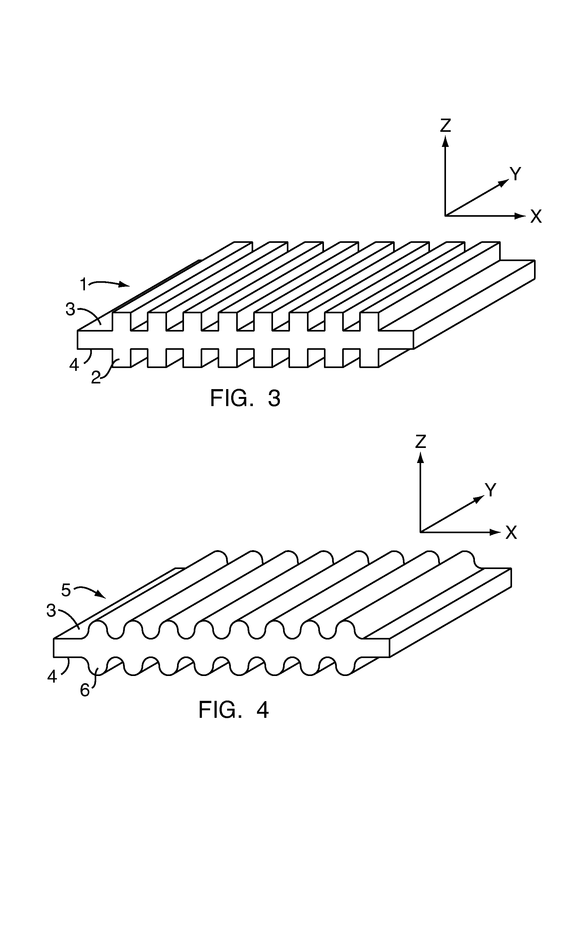
[0022]FIG. 3 indicates a corrugated elastomeric actuator 1, where the corrugation 2 has a square shape. The corrugation runs in the Y-direction according to the indicated system of co-ordinates, and the X-direction is running across the corrugation. Separate electrodes have been vaporised onto the top surface 3 and the bottom surface 4, whereby an electrical field-can be applied between the two electrodes. When the two electrodes are forced towards each other, due to the electrical field, the elastomeric core material will be squeezed in the Z-direction, and due to volume preservation it will increase in the Z-direction, leading to an increase in the X-direction, the Y-direction or both. The corrugation combined with the electrode will, however, make the X-direction far more deformable than the Y-direction, and the increase will therefore only be in the X-direction. This has previously been referred to as compliant electrodes or mechanical anisotropic properties.

[0023]The square sha...


PUM


Abstract

This invention relates to an elastic bandage for supporting a body extremity such as a leg. Such bandages are used to overcome problems with fluid retention and swelling in the legs, occurring as a consequence of varicose veins, vascular incompetence, pregnancy, etc. It is a task of this invention to supply an active support for a body extremity such as a leg, which can be used by a person underneath the clothes and will not reduce the mobility of the patient. This task is solved in that an elastic bandage comprises an elastic layer for surrounding a body extremity to exert compressive force on the extremity, the bandage being, at least partly, formed by elastomeric actuation elements, whereby electrical control of the compressive force is possible, and where the control is due to a signal from some sensing system.

Description

CROSS REFERENCE TO RELATED APPLICATIONS[0001]This application is entitled to the benefit of and incorporates by reference essential subject matter disclosed in International Patent Application No. PCT / DK2004 / 000123 filed on Feb. 24, 2004 and Danish Patent Application No. PA 2003 00277 filed Feb. 24, 2003.FIELD OF THE INVENTION[0002]This invention relates to an elastic bandage for supporting a body extremity such as a leg. Such bandage are used to overcome problems with fluid retention and swelling in the legs, occurring as a consequence of Varicose veins, vascular incompetence, pregnancy, etc.BACKGROUND OF THE INVENTION[0003]Supporting stockings used to overcome the described problems are known in a lot of variations, and are on the market in a lot of models and sizes. However, they are all passive, meaning that they are produced with a given elasticity that will decrease over time. Typically, support stockings can be used for about 6 months, whereafter they have lost the major part...

Claims


Application Information

Patent Timeline
Patent Type & Authority Patents(United States)
IPC IPC(8): A61F13/00A61F13/08A61H23/02A61H31/00
CPCA61H23/02A61H31/006A61F13/085A61H2201/10A61H2201/165A61N1/00A61H2209/00
Inventor MUNCH-FALS, JAKOBBENSLIMANE, MOHAMED YAHIAGRAVESEN, PETERSTENSTROEM, THEISS
Owner DANFOSS AS
Why Eureka
Try Eureka